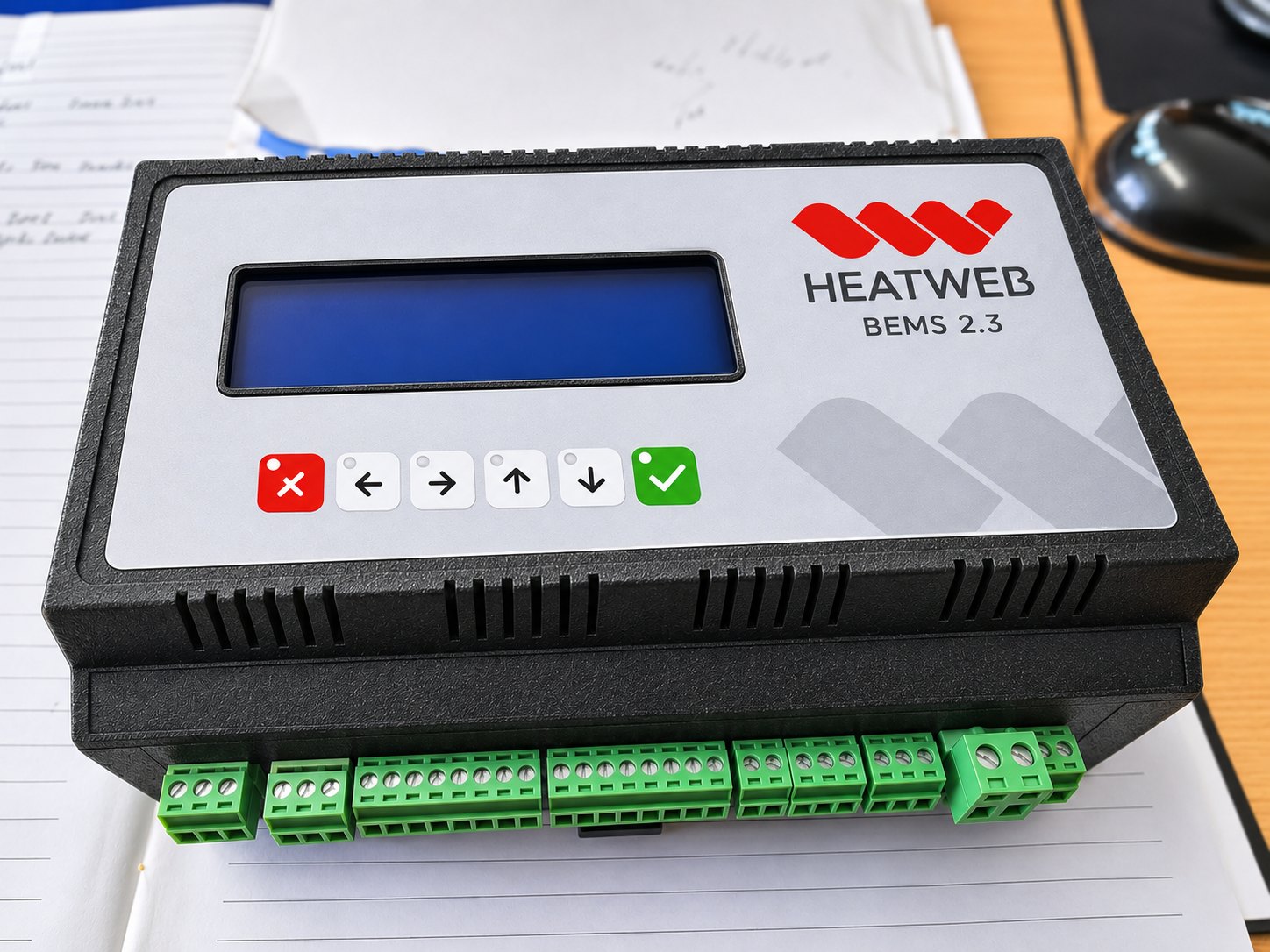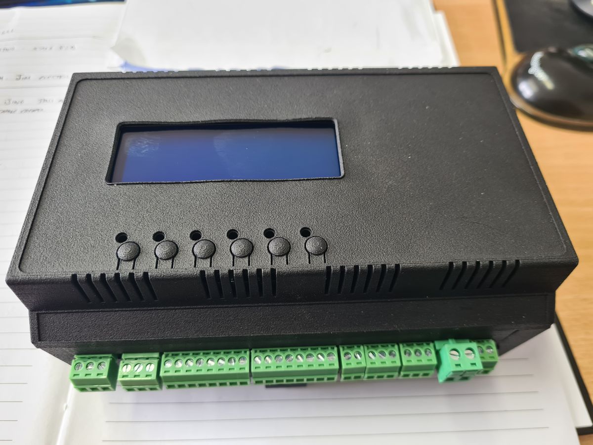
The BEMS 2.3 (Building Energy Efficiency Management Solution) controller was the main hardware outcome of our SBRI open-source controls project. This case study covers the hardware itself; the project case study covers the software, cloud systems and field trials.
The problem it solves
Monitoring a system is not enough. Heat networks and HVAC plant need their controls managed and adjusted as soon as inefficiencies appear, and operators have obligations such as the Heat Network (Metering and Billing) Regulations, which require metering and consumption-based billing. What was missing was a controller that:
- connects to almost every HVAC sensor and device
- gives both the data and the ability to control the essential parts of the system
- allows remote access, so problems can be seen and acted on quickly
- meets the security standards and certifications commercial organisations and local authorities require
- makes the data easy to analyse and report on
The I/O board
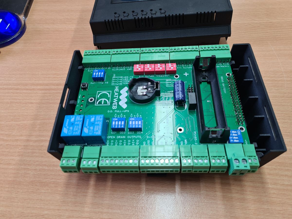
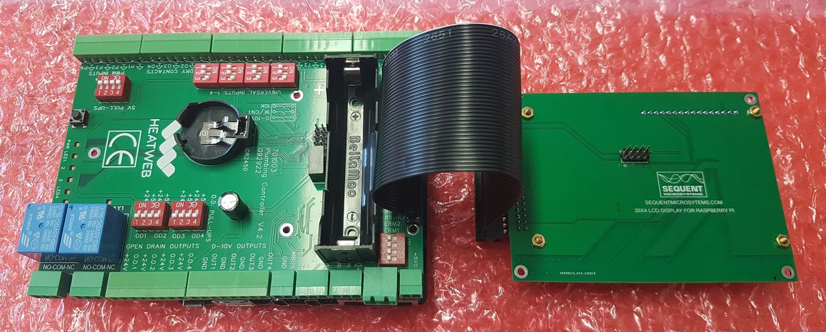
The plumbing controller I/O board does the work at the plant: it reads the sensors, meters and signals, and drives the valves, pumps and relays.
Inputs
- 8 dedicated NTC temperature sensor inputs
- 4 universal inputs for volt-free contacts, 100 Hz pulse signals, 0–10 V signals and 1k/10k NTC thermistors
- 4 volt-free / 100 Hz pulse inputs
- 4 PWM inputs with jumper-switched pull-up resistors and voltage comparators
Outputs
- 2 × 10 A change-over relays
- 4 PWM sinking outputs with jumper-switched pull-ups at 5 V and 24 V
- 4 × 0–10 V analogue outputs
Communications
- 2 RS485 lines for Modbus or bespoke protocols, with jumper-switched terminating resistors
- on-board Modbus for daisy-chaining several I/O boards
- M-Bus for heat and energy meters
Power and resilience
- runs from a single 12 V supply
- on-board battery-backed uninterruptible supply to all equipment
- uninterruptible 24 V for valves, 5 V for sensors and 36 V for M-Bus, all generated on the board
- real time clock, a general-purpose button, 3 user-definable LEDs and fan control
The processor
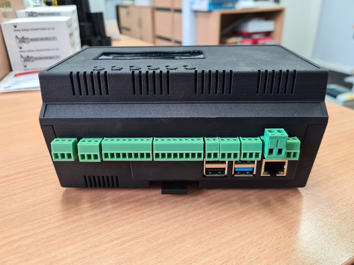
The I/O board is driven by a Raspberry Pi CM4 Compute Module: industrial grade, well developed, and available with a range of memory and processor sizes. It sits on a base board that provides USB, Ethernet and display connections, and talks to the I/O board over I2C and three UARTs.
The I/O board is deliberately open to other processors: every Raspberry Pi model, the BeagleBone and the ESP32 all work with it. Base board options include a mini base board, a dual-Ethernet base board, 4G/GSM communications and our own ESP32 board that emulates a Raspberry Pi.
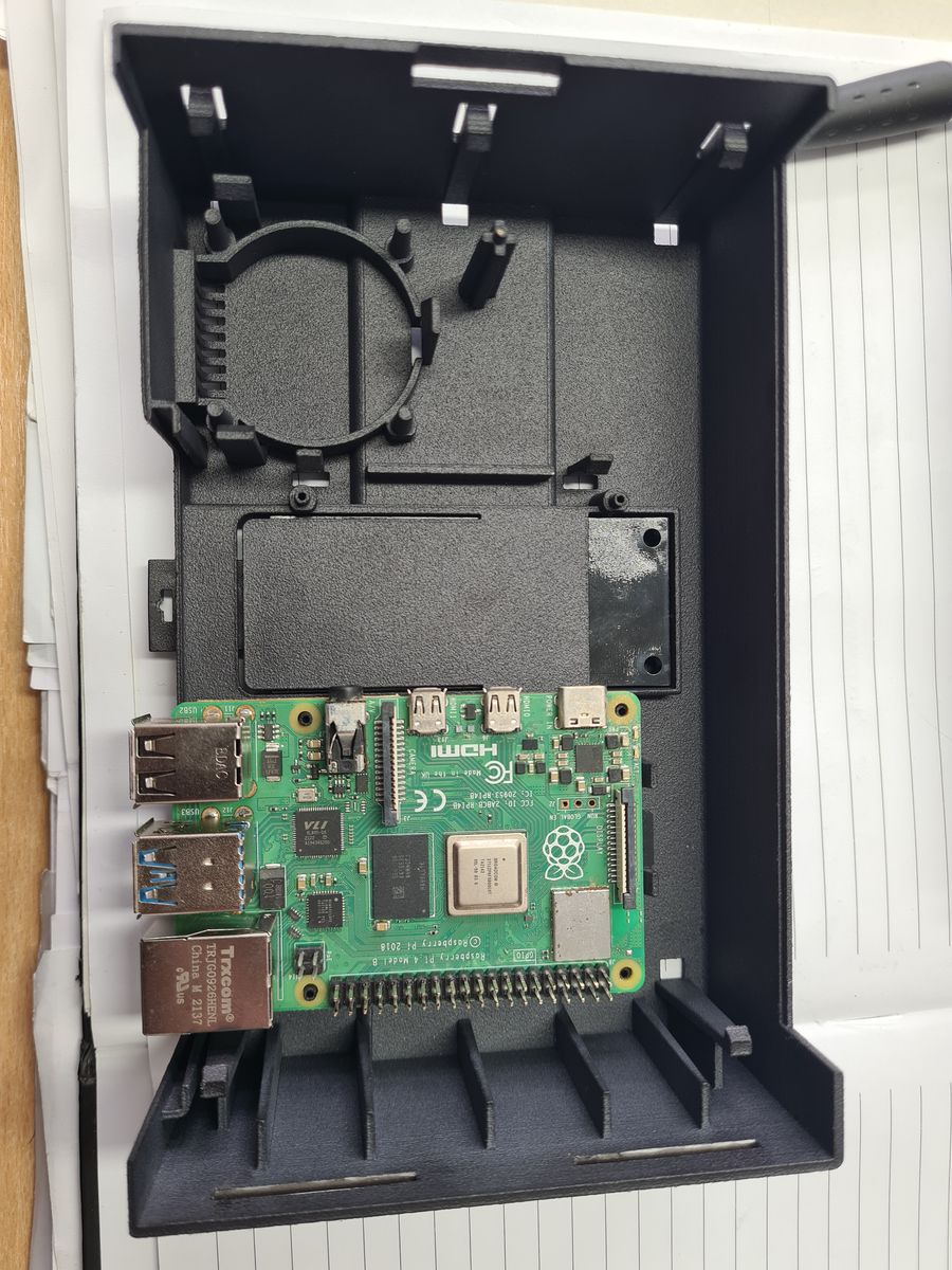
The enclosure
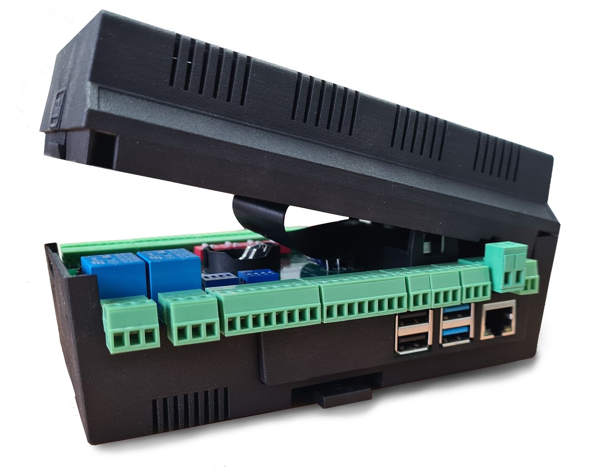
The enclosure was modelled in 3D CAD with every board in its final position before anything was made, then refined through 3D-printed prototypes to get the fit and function right:
- a DIN-rail case with the terminals along the front edge and custom terminal labels for each application
- a hinged lid over the I/O board, with a press-release clip
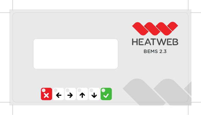
- an LCD display with six buttons for setup and status on site
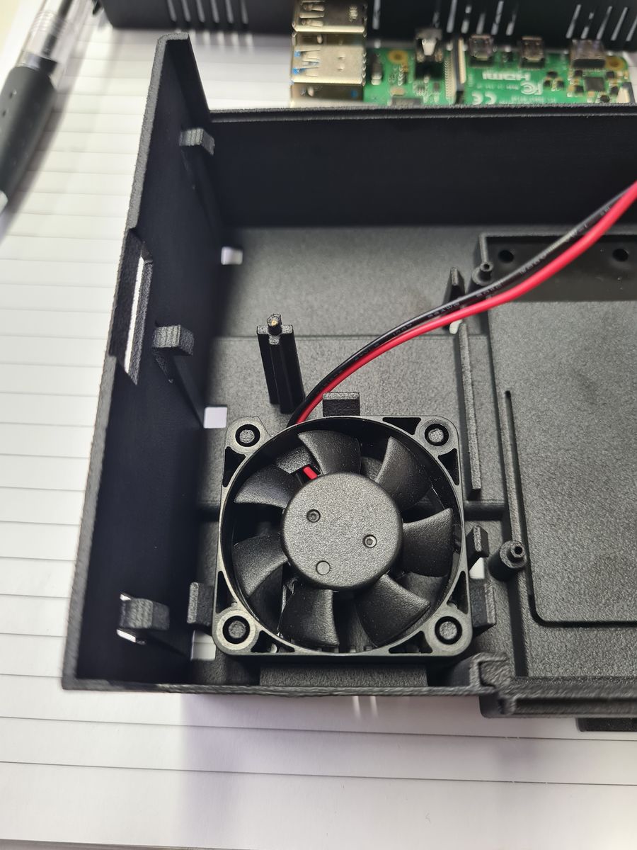
- a 40 mm cooling fan, and slots that keep the ribbon cables tidy
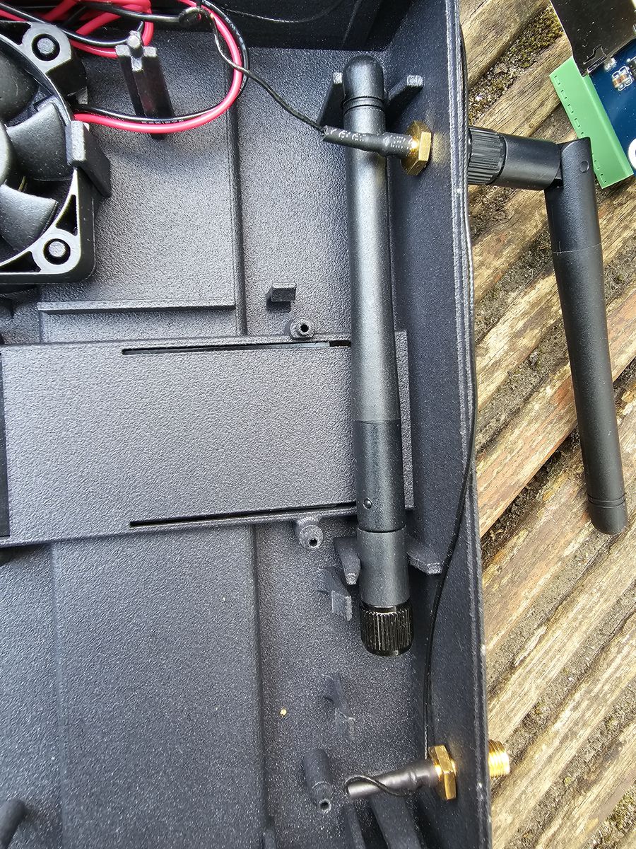
- positions for 4G and WiFi antennas, so the unit reports to the cloud from a plant room
CE certification
Every PCB developed for the controller was tested and found to comply with the EMC Directive 2014/30/EU:
| Board | Certificate |
|---|---|
| Heating controller | POCE230403637TCE |
| LCD display | POCE230403636YCE |
| ESP32 board | POCE230403635BCE |
UKCA approval, through the same approvals body, is planned for future production runs.
A range around the controller
The same hardware is built into a range so that each site gets a working system in one box:
- Plumbing I/O board: plumbing I/O, 2 × RS485, M-Bus and battery backup
- BA board: 8 universal inputs, 4 × 0–10 V outputs, 3 triac outputs, 1-Wire and RS485
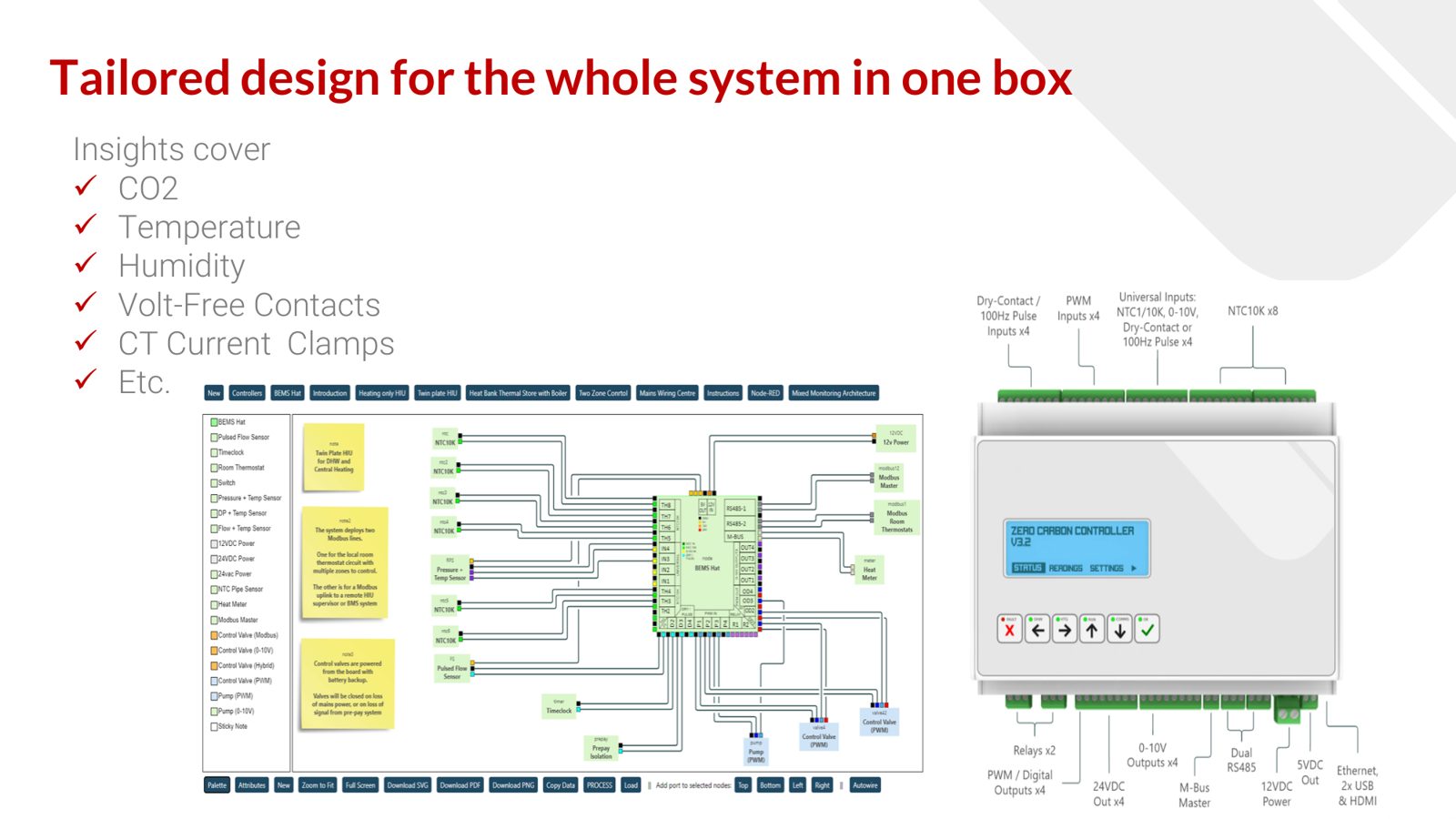
- EnOcean gateway and wireless sensors: Ethernet, WiFi and LTE, with energy-harvesting wireless sensors for CO₂, temperature, humidity, volt-free contacts, CT current clamps and more
- Application enclosures: pre-wired, customised to the application, connected to the cloud and ready to turn on
- Control panels: standard and custom, in metal cabinets with touch screens
Open software, licence-free
Everything that runs on the controller is open source and licence-free: applications run in Docker containers, logic and control are written in Node-RED, and data moves over MQTT. Installation is a single command from GitHub, and the same components run in the controller and in the cloud dashboards.
Where it runs
The controller has been installed on live systems including:
- the Excel Centre, London: monitoring and improving the control of the exhibition-hall air handling
- the National Trust's Stable Yard at Morden Hall: renewable heat from heat pumps, solar and biomass
- Swansea University's SHED: all control on the UK's first CO₂ heat pump heat network
- Putney Plaza: boilers, CHP, heat pumps and pumps around the buffer stores
- HIU monitoring, from simple mechanical units to RS485 electronic HIUs, including a new hot water HIU built on the controller