
Why controls are the bottleneck
Three things stop small and medium heat networks being run well, and none of them is the pipework.
- Skills. Competent BMS engineers are in short supply, and the shortage is sharpest in design and commissioning. Every bespoke strategy written in a proprietary tool is a strategy only a few people can read.
- Licences. Conventional BMS platforms charge by the point, by the feature and by the supervisor. Exposing one more temperature over MQTT becomes a commercial decision rather than a technical one, so it does not happen.
- Visibility. A plant room without published data runs on plausible deniability. If nobody can see the return temperature, nobody is accountable for it. The monitoring standards now being introduced, HNTAS among them, assume data is published by name, continuously, at the boundaries of the network.
None of these is solved by better pipework or a better heat interface unit. They are solved by making the control layer open, inexpensive and readable.
What a WAGO node is
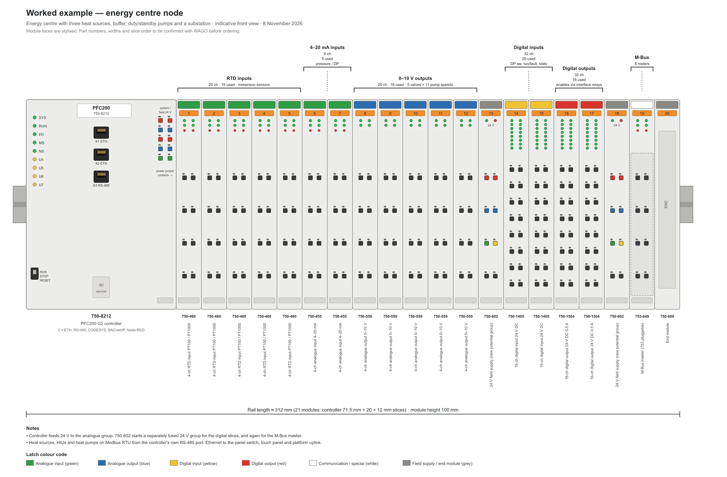
WAGO's 750-series I/O system is a controller with a row of 12 mm I/O slices clipped to it on a DIN rail. The controller runs an IEC 61131-3 runtime (CODESYS), and the slices are chosen to suit the plant: RTD inputs for immersion sensors, 4–20 mA inputs for pressure and differential-pressure transmitters, 0–10 V outputs for valves and pump speeds, digital inputs and outputs for run, fault and enable signals, and communication slices for M-Bus meters and Modbus RTU equipment. A colour on each slice's latch says what kind of channel it carries.
The controller itself brings:
- Two Ethernet ports and an RS-485 port, so Modbus RTU equipment such as pumps, heat sources and heat interface units connects without an extra module.
- Native MQTT from the runtime, and an optional BACnet/IP licence that makes the controller a listed building controller (B-BC), so a conventional BMS can discover it.
- A Linux operating system with Docker, so Node-RED, a local broker or a small dashboard can run on the controller itself. A VPN or mesh client for remote service runs the same way.
- A web visualisation served by the runtime, which a panel touchscreen or a laptop browser displays without separate HMI software.
For a very small plant room the same firmware runs on WAGO's Compact Controller 100, which has a fixed set of inputs and outputs built in and no slice expansion. The second substation drawing below uses it.
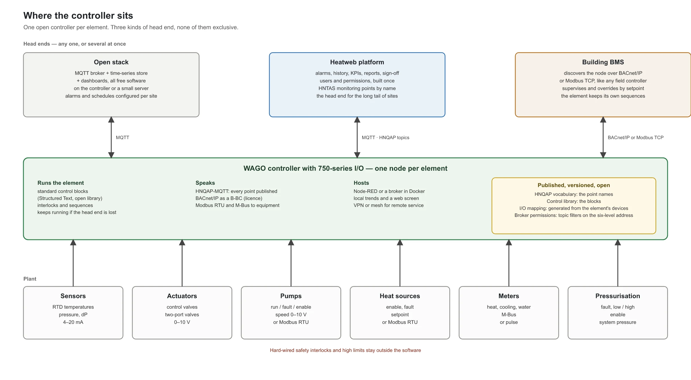
Where it sits
A controller like this is a field controller, not a BMS. It runs the element it is wired to: the staging, the pump duty and standby, the interlocks, the setpoints. Whether the head end is alive or not, the element keeps running. Above it there are three kinds of head end, and they are not exclusive.
- An open stack. An MQTT broker, a time-series store and a dashboard tool, all free software, running on the controller or on a small server. It gives live views and history in minutes once the topics follow the protocol. Alarms and schedules have to be configured per site.
- The Heatweb platform. Alarms, history, KPIs, reports, sign-off, users and permissions, built once for every site, with the HNTAS monitoring points recognised by name. This is the head end we intend for the long tail of sites that will never buy a BMS.
- A building BMS. With the BACnet/IP licence the controller appears to a conventional BMS like any other field controller. The BMS supervises, trends and overrides by setpoint. The element keeps its own sequences. Modbus TCP is available as well, without a licence.
So the proposition to a consultant or an estate is not "replace your BMS". It is "here is the heat-network controller your BMS talks to, and it works on its own when there is no BMS".
What the open stack does not give you
A dashboard app shows what is published. It does not, by itself, manage alarms with escalation and acknowledgement, hold time schedules, or keep an audit of who changed what. Schedules live on the controller. Alarms and audit need either the platform or a rules layer configured per site. That is the honest difference between a cheap head end and a complete one.
A standard substation element
A substation is the most common element on a heat network and the best candidate for a standard wiring centre. The substation standard we work to is a twin-plate station: primary flow and return through two plate heat exchangers in parallel, a modulating control valve with position feedback per plate on the primary side, a spring-return two-port isolation valve with end switches per plate on the secondary side, strainers with differential-pressure measurement, pressure transmitters on both sides, a heat meter on the primary return as the intake boundary meter, and a twin-head variable-speed distribution pump and a pressurisation unit downstream. Simpler stations are subsets of it.
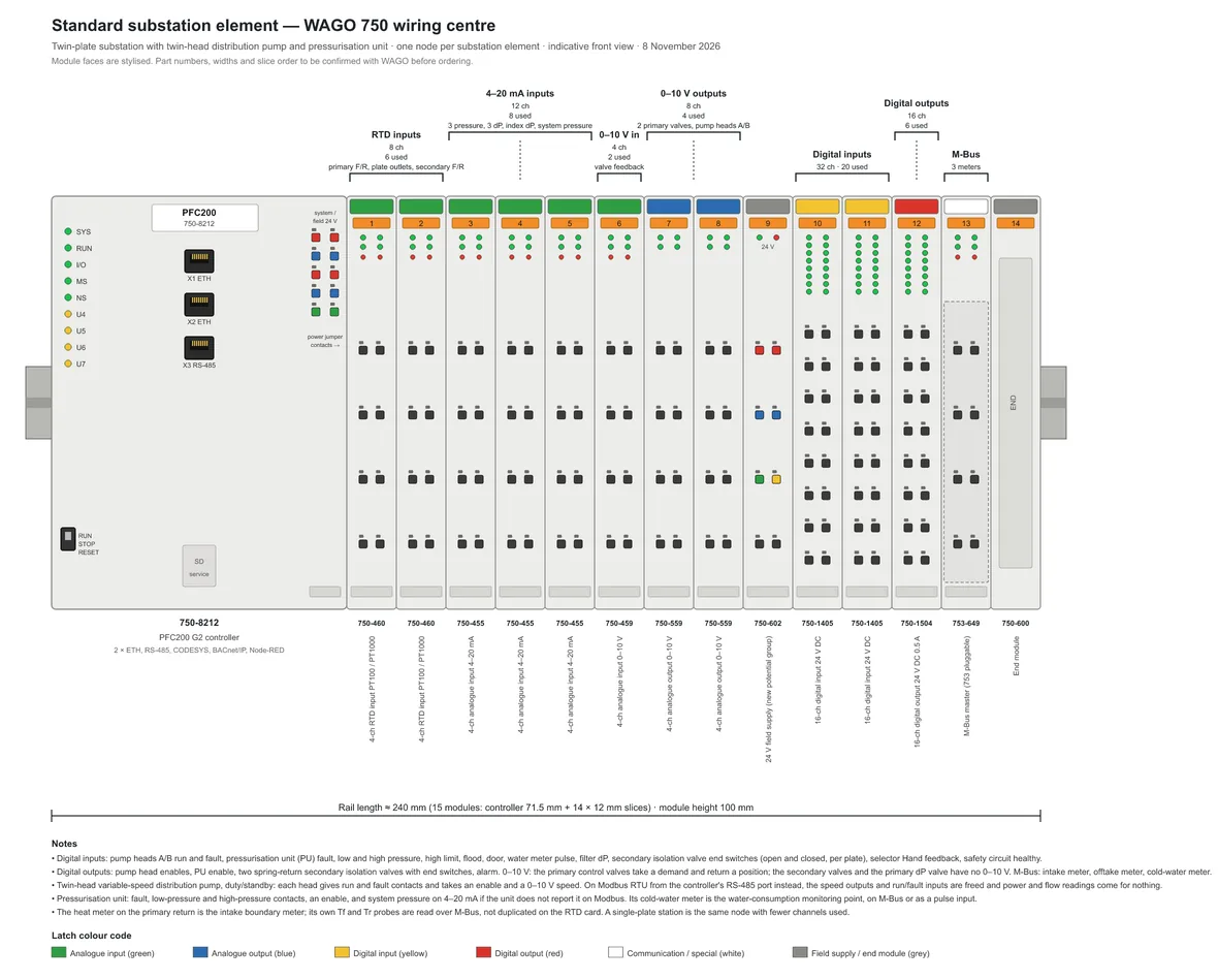
| Signal | Channels | Points |
|---|---|---|
| RTD inputs | 8, 6 used | primary flow and return, plate secondary outlets ×2, secondary flow and return |
| 4–20 mA inputs | 12, 8 used | three pressures, three differential pressures, index differential pressure, system pressure |
| 0–10 V inputs | 4, 2 used | position feedback from the two primary control valves |
| 0–10 V outputs | 8, 4 used | two primary control valves, pump heads A and B |
| Digital inputs | 32, 21 used | pump heads run and fault, pressurisation on, low and high pressure, high limit, flood, door, water-meter pulse, filter dP, secondary valve end switches open and closed, four selectors in Hand, safety circuit healthy |
| Digital outputs | 16, 5 used | pump head enables, two secondary isolation valves, alarm |
| M-Bus | 3 meters | intake heat meter, offtake heat meter, cold-water meter |
| Modbus RTU | on the controller | distribution pump, pressurisation unit where it offers it |
Two design points are worth stating:
- The heat meter is a sensor. It already measures primary flow and return temperature and flow rate to billing accuracy. Read over M-Bus, those values are not duplicated on the RTD card, and the controller publishes the intake boundary meter the monitoring standard asks for.
- Put the pump on the bus where the range allows it. A twin-head pump on Modbus RTU frees two analogue outputs and four digital inputs and reports power and flow for nothing. The fault contacts stay hard-wired.
From the node to the field terminals
Between the controller and the field sits a layer that keeps working with the controller switched off: an interposing relay on every output and on each input that has a panel lamp, a Hand-Off-Auto selector for each pump head and for each plate, a hard-wired safety relay fed by the high limit and the flood switch, and the lamps. In Hand, a changeover relay behind each selector feeds the pump or the primary control valve its 0–10 V from a potentiometer on the door instead of from the controller, one for the pumps and one for the control valves, and a plate in Hand holds its secondary isolation valve open. Each plate has a green running lamp driven by its secondary valve's open end switch. The pressurisation unit runs on its own controls and is monitored only, with on, low-pressure and high-pressure lamps. Below it, a numbered row of DIN rail terminals is the only place a field cable lands. We draw this as a current-path schematic to IEC 61082, the format panel builders already read: supply potentials as horizontal rails, eight numbered paths per A3 sheet, one channel per path, cross-references as sheet and path. A larger station adds sheets, not density, and the terminal and device schedules at the back are generated from the same point list as the paths.
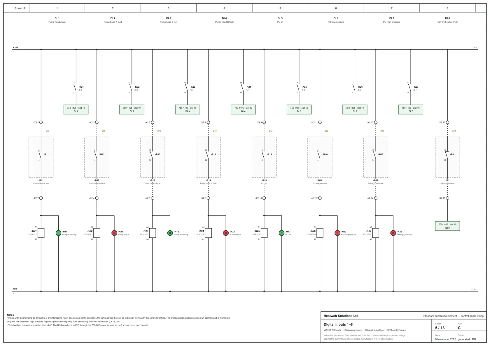
The full set is a PDF: Standard substation element, control panel wiring, 13 sheets A3. It is indicative and not for construction. Module pin-outs and ratings must be checked against the current data sheets, and the relay, selector and lamp makes are the panel builder's choice.
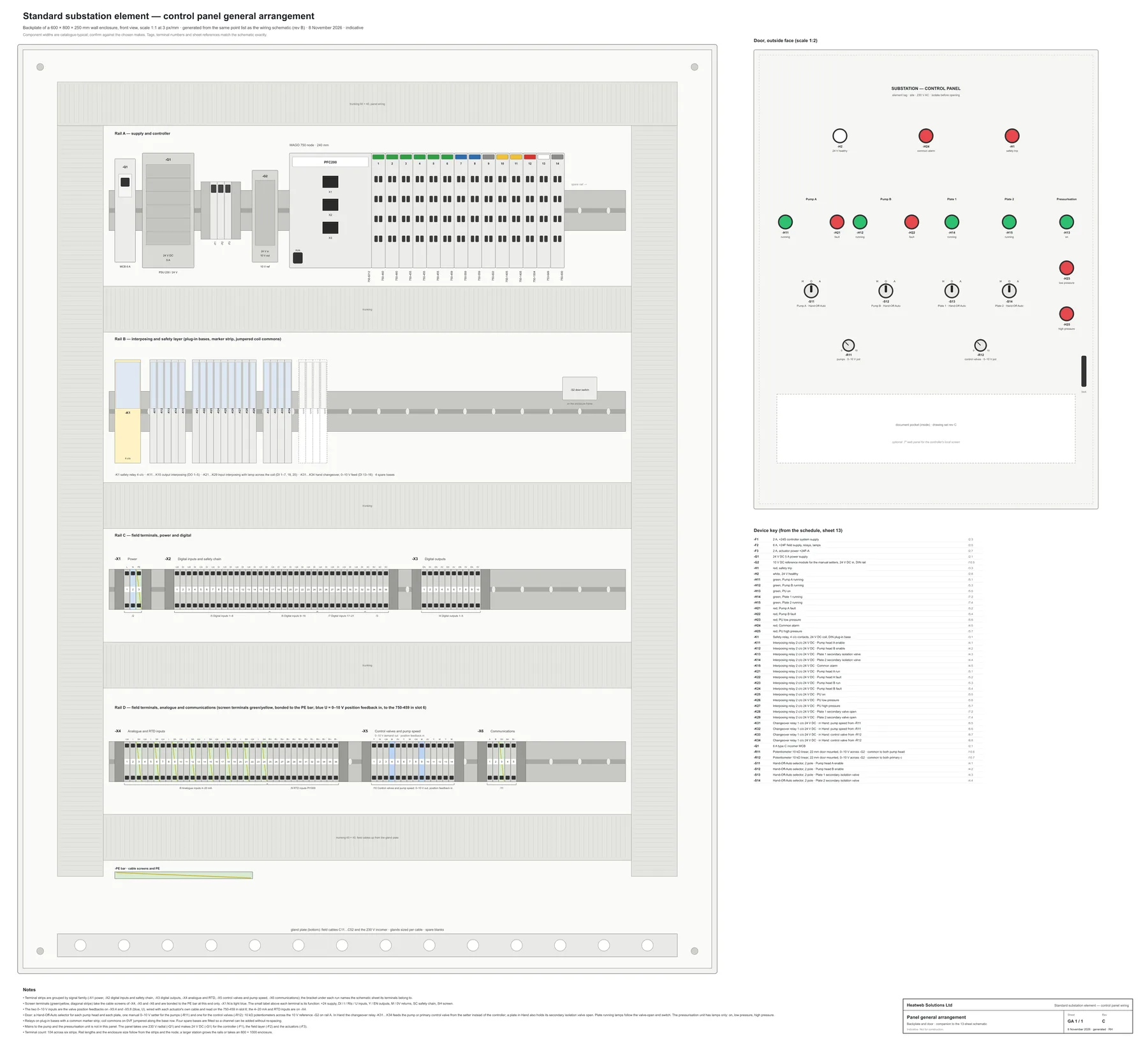
The same point list also produces the panel's general arrangement: the backplate with its four DIN rails, every terminal with its function marked, and the door.
The minimum station
Where a station has one plate, no differential-pressure transmitters and a heat meter that can speak Modbus, the Compact Controller 100 is enough on its own.
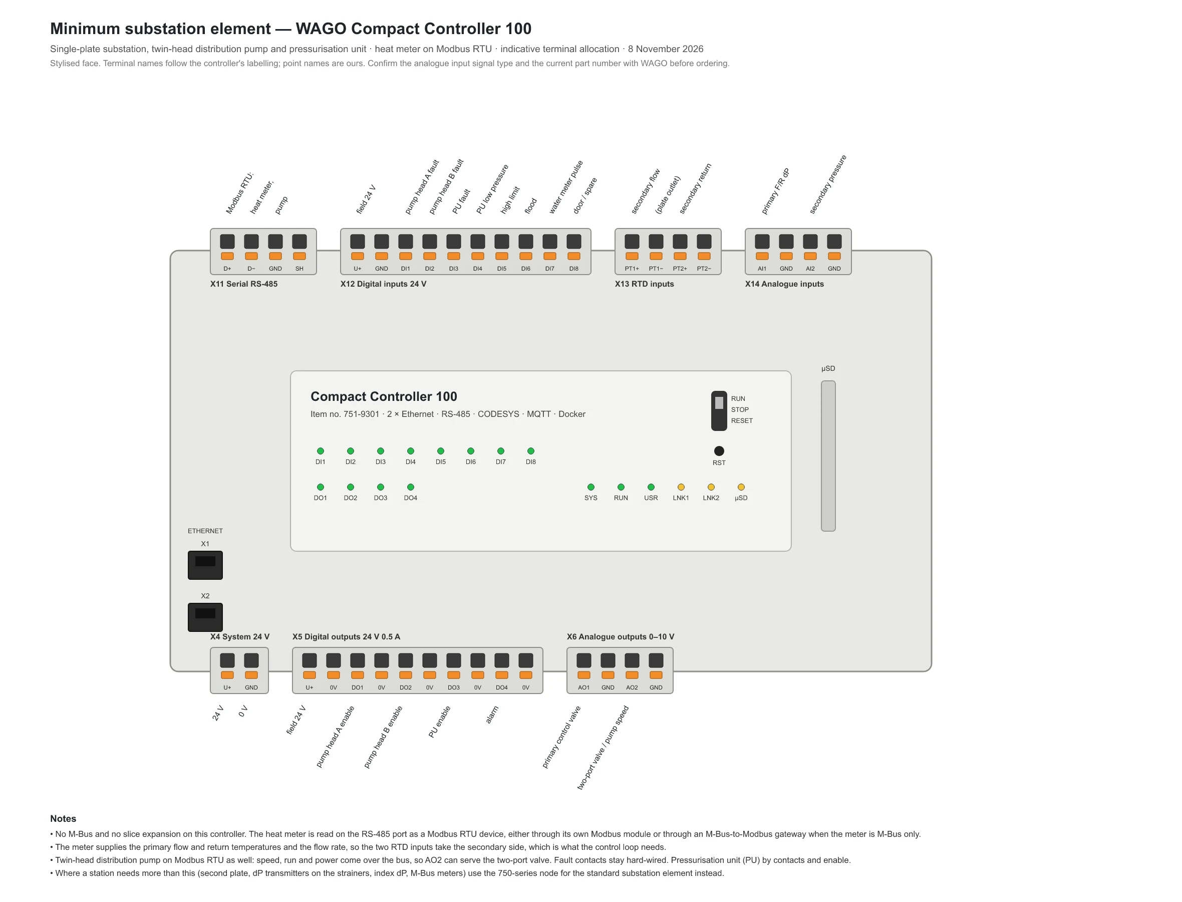
The Compact Controller has no M-Bus and no slice expansion, so the heat meter is read as a Modbus RTU device, either through its own Modbus module or through an M-Bus-to-Modbus gateway when the meter is M-Bus only. If a station needs more than this, the 750-series node above is the answer, and the price difference is a few hundred pounds rather than a different class of product.
A worked energy centre
The same approach scales to an energy centre. The drawing below is a node for an energy centre with three heat sources, a buffer, duty and standby pumps and a substation: twenty-one modules on about 312 mm of rail, with the heat sources and heat interface units on Modbus RTU and the meters on M-Bus. Two such nodes, one per energy centre, cover a two-primary plant room.
An open control library
The hardware is the smaller half of the argument. The larger half is that the control logic is Structured Text, a documented open language that runs in near-identical form on controllers from several manufacturers, and that it lives in a public repository.
- Readable in ten years. Text in a Git repository can be diffed, reviewed and explained. An engineer who has never seen the site can paste a function block into an AI assistant and ask what it does, why the pump staged, or how to add a second buffer. A strategy locked in a proprietary graphical tool, behind a licence and a training course, cannot be read that way, and the cohort trained on those tools is retiring.
- Portable beyond the vendor. If one controller range disappears, the project moves to another runtime that speaks the same language. The exported PLCopen XML is the long-term archive.
- Pinned and tested. The repository carries the toolchain version, a plant simulation block so changes can be tried off the live system, and acceptance tests for each block. That, not the blocks alone, is what makes a change by a stranger safe.
- Licensed permissively, alongside the published vocabulary of point names, so the control blocks become the next layer of the same open standard.
Two guard rails are not negotiable. Safety interlocks and high limits stay hard-wired, outside the software. And changes go to a bench controller first, with the repository history as the audit trail.
Data, permissions and remote access
Every point the controller holds is published under the six-level address of the open heat-network protocol: schema, network, element, device, vargroup, varkey. The names come from the public vocabulary, so hmeter/kwh means a heat meter's energy register on every site.
That address does most of the permissions work. A broker grants read or write per topic pattern, so a client reads its own network, an engineer writes to one element, and nobody else sees either. TLS with client certificates makes the credential the device rather than a password.
The important rule sits in the controller, not the broker. Only whitelisted writable keys are accepted, each with a range check, only on the command topic, and the new value is echoed on the state topic so every write is visible and logged. Remote service is over a VPN or mesh client running on the controller, never a port opened to the internet.
From the element model to the panel
On the Heatweb platform a substation or energy centre is an element with devices on it: pumps, valves, sensors, meters, heat sources. Each device type can carry an I/O signature. A variable-speed pump is run, fault, enable and speed, or a Modbus address. A heat meter is an M-Bus slave. An immersion sensor is an RTD channel.
From that, the wiring centre follows mechanically: sum the channels by type, add spares, choose the slices, assign the terminals, respect the supply groups. The outputs are the front view you see on this page, a terminal and cable schedule, a priced parts list, and, because the controller's address map follows the slice order deterministically, the variable list for the control project with names taken straight from the vocabulary. We are building this as a controls module of the platform, so that adding a pump to an element adds its I/O to the panel.
What it costs, honestly
The hardware for a substation node is low thousands of pounds, and for an energy centre node a few thousand more. That is not where a conventional BMS quotation goes. Most of it is design, panel build, field wiring, graphics and integrator time, and the panel and wiring labour do not disappear with a different controller.
What does disappear is the supervisor licence, the per-point charges, the proprietary tooling and the dependency on a specialist to expose one more value. For a small communal network the realistic outcome is a controls package at a third to a half of a conventional BMS upgrade, with every point published from day one. For a large building with a BMS already in place, the saving is smaller and the gain is a standard, readable heat-network controller the BMS can talk to.
Standards as they evolve
A new monitoring point or KPI input in the standard is a new name in the vocabulary and a new published topic. No per-point licence, no supervisor upgrade, no site visit to expose it. The vocabulary and the control library move in public, versioned, and the sites follow with an update to the project. That is the property that lets a plant room commissioned this year still comply with a standard that has moved on in five.
Status and caveats
- Drawings on this page are indicative front views. Module faces are stylised, part numbers are from the current WAGO catalogue as we understand it and must be confirmed with WAGO before ordering, and the Compact Controller's analogue input signal type should be checked against the transmitters chosen.
- Heatweb is independent of WAGO. This page describes how we intend to use their products, not a WAGO offering.
- The control library and the platform's controls module are in development. The protocol, the vocabulary and the platform are live.
Related reading: Heat Network Protocol, Software, Control, metering and monitoring.