
Why this page exists
A patent application is a careful description of a problem and one way of solving it. Long after the patent has lapsed, that description is still the clearest record of what the engineers were thinking at the time, and why. Our copies are paper and scanned PDFs, so this page collects them in one place with a summary of each, and sets them against the public register.
Two terms from the register are used throughout:
- Ceased. The patent was granted and later lapsed because the annual renewal was no longer paid. These were real patents and were in force for the years shown.
- Terminated. The application was published but was not pursued to grant, usually because the product had moved on before examination finished. The published specification still stands as prior art.
A lapsed patent cannot be enforced by anyone, and the ideas in it are free to use.
The specifications we hold
Six documents survive in our files: four applications as filed with the UK Intellectual Property Office, and two internal invention disclosures that were written up in the same form but, as far as the register shows, never filed.
Overheat protection for thermal stores
| Application | GB0909526.6, filed 3 June 2009 |
| Publication | GB2470748, 8 December 2010 |
| Outcome | Granted 28 February 2012. Renewed to the ninth year, ceased 3 June 2018. |
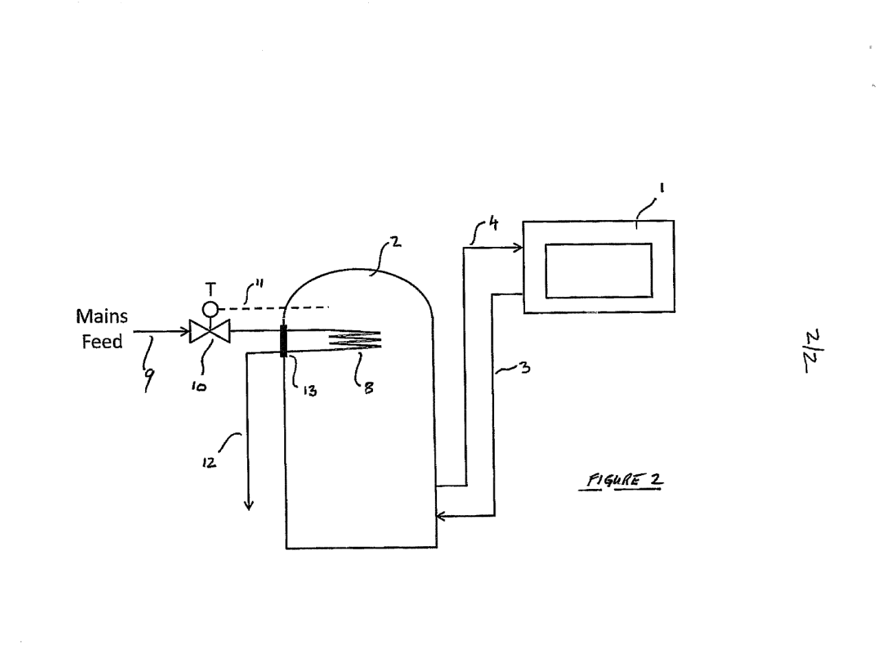
The problem. A thermal store fed by a wood burner or a solar collector cannot simply switch its heat source off when the water gets too hot, and an electrically controlled dump is useless in a power cut. The conventional answer was a gravity-fed bypass radiator, which wastes heat all year and gets isolated by the householder because the room is too warm.
The idea. Put a heat exchange coil inside the top of the store, feed it with cold mains water through a purely mechanical thermostatic valve, and run the outlet to a drain. The valve opens only when the store passes a set temperature, so heat is dumped only when the store would otherwise boil, and the protection works with no electricity at all. The coil sits on a standard 2¼ inch BSP immersion-heater boss, so it can be retrofitted to an existing cylinder, and the specification recommends that stores be made with two or three such bosses for the purpose. A copper coil on that boss was found to shed as much as 25 kW with a 10 °C mains feed and a 95 °C valve setting.
What it claimed. An overheat protection system comprising a heat exchange unit in thermal connection with the store, a cold water connection to it, a thermostatic valve assembly that admits cold water when the store exceeds a pre-set temperature, and a means of discharging the water. Dependent claims cover the coil inside the store, mains cold water, and a valve that needs no power.
This is the mechanism that shipped in the Xcel range of thermal stores, and the specification cross-references two earlier co-pending applications on flue gas heat recovery.
Download: Specification on file as at 18 November 2011, with amended claims (PDF, 260 KB)
Fluid heating and storage with a weather compensating boiler
| Application | GB1302898.0, filed 19 February 2013, claiming priority from GB1215072.8 of 23 August 2012 |
| Publication | GB2505263, 26 February 2014 |
| Outcome | Examination requested August 2014. Terminated 16 August 2018, not pursued to grant. |
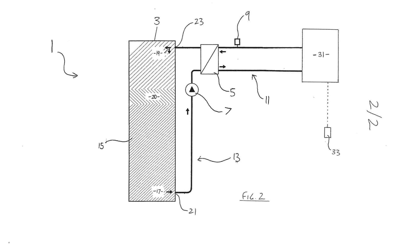
The problem. A stratified cylinder is recharged by pumping cool water from its base through an external plate heat exchanger and returning it to the top. If the boiler side is not yet hot, that loop delivers lukewarm water to the top of the store and destroys the hot layer that the taps depend on. The delay is short with a small gas boiler but long with high thermal-mass boilers, with central plant feeding many cylinders through long pipework, and above all with a weather compensating boiler, which deliberately runs cool in mild weather. Mains-pressure hot water needs the boiler at 65 °C or more, while compensated heating may be content with 40 to 50 °C.
The idea. Interlock the store pump with the temperature of the boiler flow arriving at the heat exchanger. A thermostat on the boiler flow blocks every run signal to the store pump until the boiler water is hot enough to heat the store properly. The boiler is then free to run compensated for the heating most of the time, and when it lifts to full temperature, on a timer, on demand or in cold weather, the store recharges. The result is a compensated boiler that still delivers 60 °C stored water for mains-pressure hot water, which is exactly the conflict that stopped weather compensation being used on systems with cylinders.
What it claimed. A fluid heating and storage apparatus with a heater whose output responds to air temperature, a store, a heat exchanger between them, and a control system that controls flow of the store fluid through the exchanger depending on the heater's output. Dependent claims cover permitting flow only above a pre-determined boiler temperature, the two operating modes, the thermostat and pump interlock, and a kit for retrofitting the control to an existing system.
Download: Specification as filed 19 February 2013 (PDF, 970 KB)
Pre-heating a boiler from its own store
| Application | GB1215080.1, filed 23 August 2012, jointly with a partner company |
| Publication | GB2506582, 9 April 2014 |
| Outcome | Examination requested October 2014. Terminated 1 September 2018, not pursued to grant. |
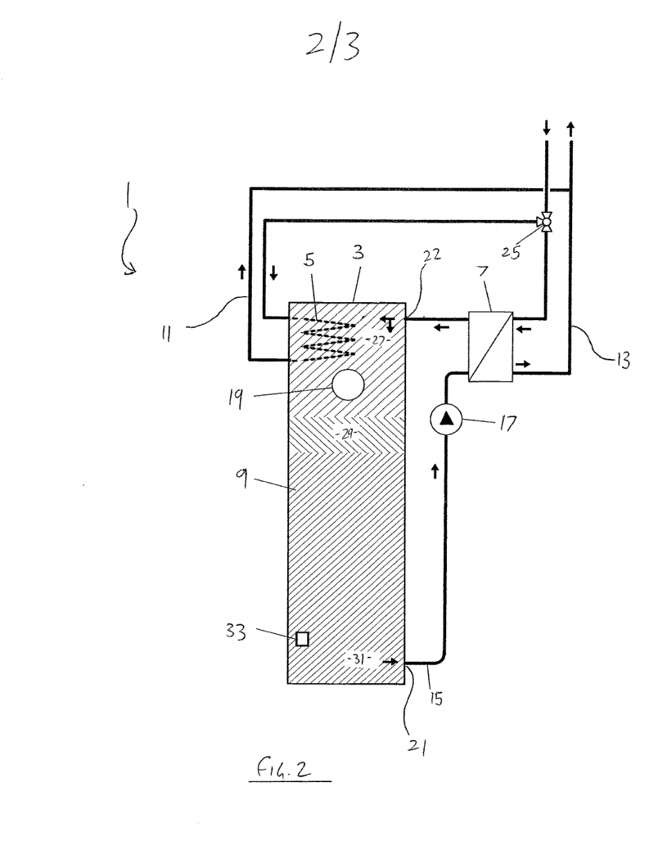
The problem. Some boilers cannot start cold. A boiler burning waste vegetable oil, or a small combined heat and power engine, has to be brought up to around 50 °C before it will ignite or run cleanly. After a night off, its water jacket is cold while the store it feeds is still warm.
The idea. Run the system backwards for a few minutes. A coil in the hot top of the store, or the plate heat exchanger used for normal charging, warms the boiler's own circulating water from the stored heat, and the warm water is pumped through the boiler until it reaches starting temperature. A diverter valve then swaps the circuit over and the boiler re-heats the store in the normal way, from the top down through a plate exchanger or from the bottom through a second coil. If the store is cold too, an immersion heater warms just the top layer around the coil. The specification notes that the idea looks counterintuitive, since it spends stored heat the system was designed to keep, but that a short pre-heat is cheaper than keeping the boiler warm all night.
What it claimed. An apparatus for pre-heating a fluid heater, comprising a store, the heater, a heat exchanger between them and a circuit for the heater's fluid, where that circulation is controllable so that the stored fluid heats the heater's fluid and delivers it to the heater. Dependent claims cover taking the heat from the top or the bottom of the store, a coil or a plate exchanger, the additional re-heat circuit, the diverter valve and a kit.
Download: Application as filed 23 August 2012 (PDF, 730 KB)
Networked heat interface units
| Application | GB1413046.2, filed 23 July 2014, working title "Networked HIUs" |
| Publication | GB2528478, 27 January 2016, "Controlling total system output of multiple heating units" |
| Outcome | Examination requested July 2016. Terminated 19 February 2020, not pursued to grant. |
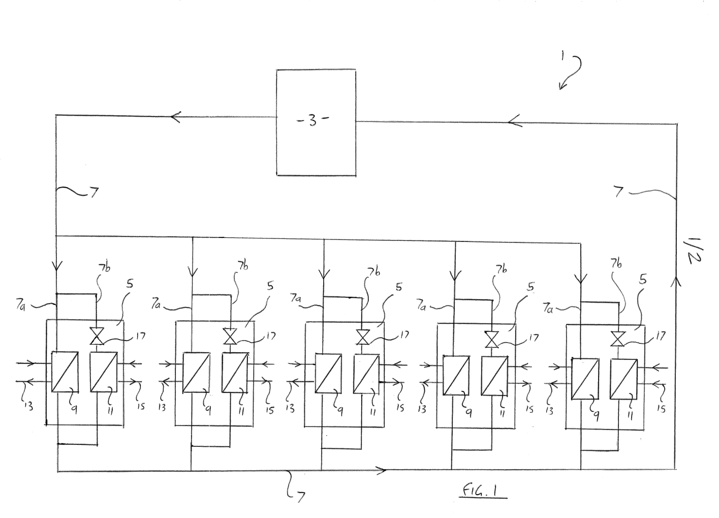
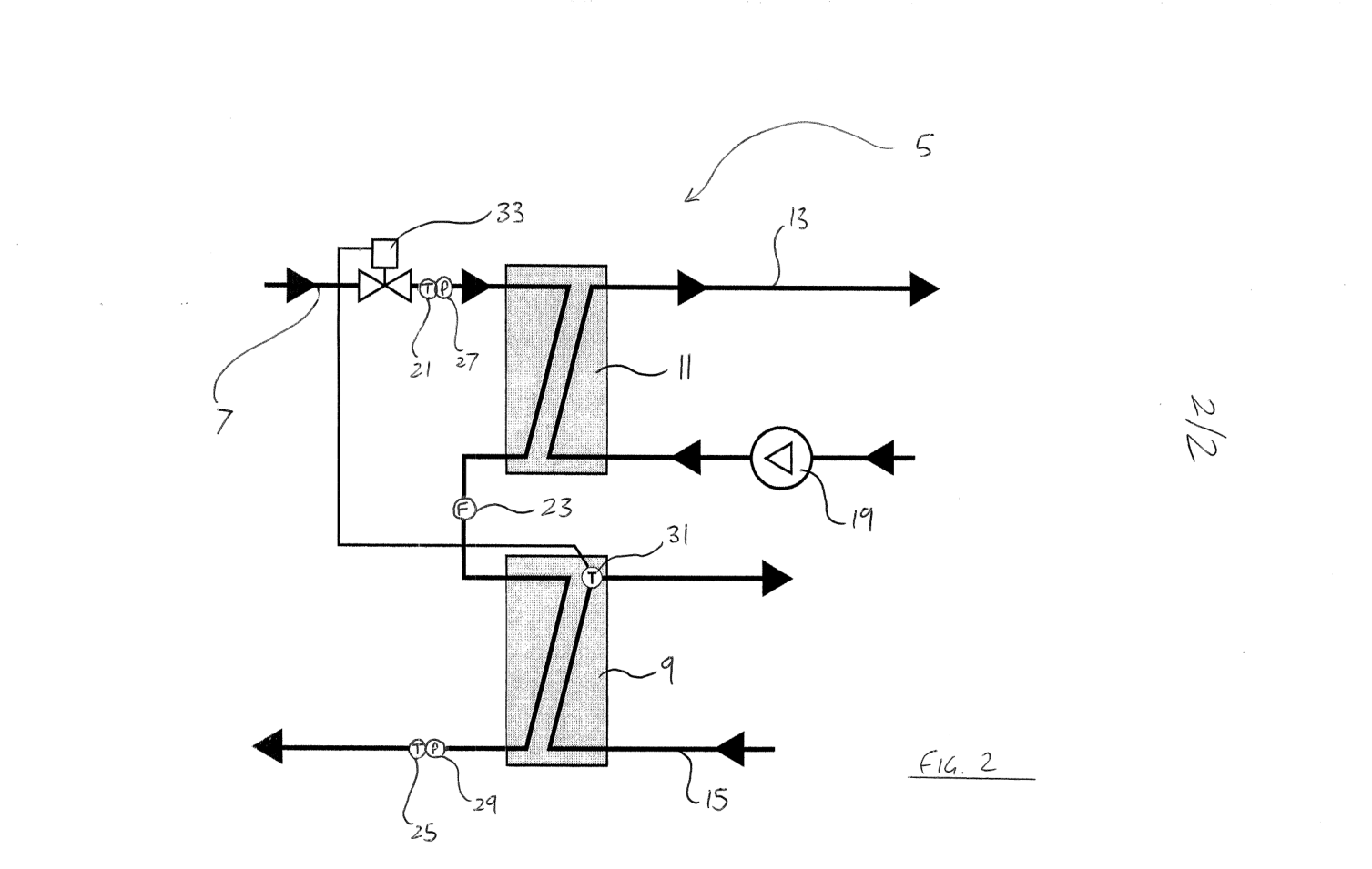
The problem. The size of a central plant, and so whether a heat network is viable at all, is set by the peak load. Interface units in each home draw whatever they want whenever they want it, so the plant and the pipework have to be sized for the worst coincidence of hot water and heating demand, with a diversity factor that is at best a guess.
The idea. Treat the interface units as one controllable system. Every unit measures its own output from flow and temperatures, and can throttle its heating output through its primary control valve or pump. The units report to a server, or form a peer-to-peer network among themselves, and the total system output is compared with a limit. When the network approaches the limit, heating outputs are trimmed across the units while hot water, which is short and urgent, keeps priority. A unit can also react on its own to conditions it sees in the primary fluid, such as a falling flow temperature or pressure, so the scheme degrades gracefully if communication fails. The plant can then be sized for a managed peak rather than a theoretical one, and more homes can be served by the same plant and pipes.
What it claimed. A fluid-heating system with a plurality of heating units each generating a heating and a hot water output under a controller, and a source of heated primary fluid, in which the system regulates the total system output by controlling the heating output of each unit. Dependent claims cover output sensors and a limit, reporting to a server, the peer-to-peer variant, sensing of primary conditions, the two exchangers in series or parallel, the valve or variable-speed pump as controller, and a computerised method that receives unit outputs, totals them, compares them with the limit and signals reductions.
Of all the applications on this page this is the one closest to what we do today. The measurement, communication and network-wide limiting described in 2014 are what our platform now does with live meter and sensor data across a whole network, and the follow-on application of 2015 on interface unit communication over M-Bus took the same direction.
Download: Application as filed 23 July 2014 (PDF, 435 KB)
CylBoss: a retrofit connection for a storage vessel
| Document | Invention disclosure dated 26 April 2012, written as a patent application |
| Register | No filing under the company name appears on the UK register. An earlier granted patent on the same theme, GB2266131, a boss for connecting a pipe to a cylinder or tank, was filed personally in 1993 and ceased in 1997. |
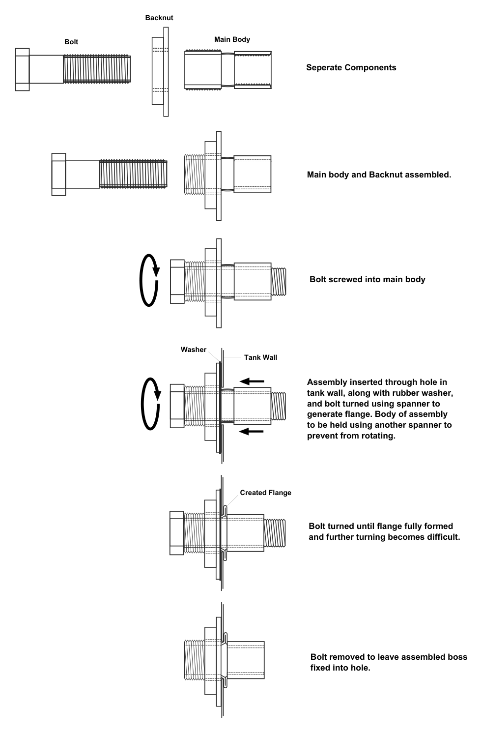
The problem. Adding a pipework connection to an existing cylinder or tank normally means getting inside it, or welding or brazing to the outside, neither of which is practical on site.
The idea. A copper fitting that forms its own internal flange, in the way a pop rivet does. A hole is drilled in the tank wall, the fitting is pushed through with a washer, and a reusable bolt screwed into the body is tightened from outside. The bolt pulls the back of the fitting in and a pre-shaped annealed section deforms into a flange against the inside of the wall. The bolt is removed and a backnut finishes the joint. A split backnut, or flats on the body, let the fitting be gripped so it cannot rotate while the flange forms. The disclosure covers a range of sizes and threads, and a one-piece variant without a separate backnut.
Download: CylBoss disclosure (PDF, 100 KB)
Thermostatic circulation control for a store charged through a plate heat exchanger
| Document | Invention disclosure dated 20 April 2013, "Thermostatic circulation control for hot water stores using an external heat exchanger for recovery" |
| Register | No filing under the company name appears on the UK register. |
The problem. When a store is charged through an external plate heat exchanger, the temperature of the water going back into the top of the store depends on how fast it is pumped: slow circulation approaches the boiler flow temperature, fast circulation falls short of the target. Boilers, and especially sources whose output you want to take in full such as biomass or recovered heat, do not deliver a constant input, so a fixed pump speed gives either scalding or lukewarm water at the top of the store.
The idea. Put an ordinary three-port thermostatic blending valve in series on the heat exchanger outlet, with both of its inlet ports fed from that same hot outlet, but with a restriction in the pipe to the hot port. When the delivered water is below the valve's set point the valve draws more from its restricted hot port, the circulation rate falls and the water gets hotter. When it is above the set point the valve draws from the unrestricted cold port, flow rises and the water cools. The valve therefore modulates the circulation rate to hold the set temperature with no sensors, controller or variable-speed pump, and it takes whatever heat the source has to give. The size of the restriction sets the minimum flow and so the lowest boiler input the loop can match.
Download: Disclosure note with schematic (PDF, 20 KB)
The full register
The UK register lists fifteen applications by Thermal Integration Limited, the company that became Heatweb, and a further thirteen by the same inventors under earlier companies or in their own names. Every entry links to the register, where the published specification can be read through Espacenet. None is in force.
Thermal Integration Limited, 1998 to 2015
| Application | Publication | Title | Filed | Outcome |
|---|---|---|---|---|
| GB9813773.0 | GB2326703 | Hot water supply systems | 25 Jun 1998 | Granted 19 Mar 2002. Renewed to year 19, ceased 25 Jun 2017. |
| GB0014034.3 | GB2352506 | Water heating apparatus (mains-pressure water through a heat exchanger from a primary circuit) | 8 Jun 2000 | Granted 7 Oct 2003. Renewed to year 17, ceased 8 Jun 2017. |
| GB0909526.6 | GB2470748 | Overheat protection system | 3 Jun 2009 | Granted 28 Feb 2012. Renewed to year 9, ceased 3 Jun 2018. |
| GB1112929.3 | – | Water heating system | 27 Jul 2011 | Priority filing, replaced by the application below. Terminated 28 Jul 2012. |
| GB1117688.0 | GB2493222 | Water heating system for heating mains water using a thermal store | 13 Oct 2011 | Published 30 Jan 2013. Terminated 16 Feb 2018. |
| GB1116914.1 | GB2495905 | Water heating system arranged to heat mains pressure water using a thermal store and a heat exchanger | 30 Sep 2011 | Published 1 May 2013. Terminated 20 Feb 2018. |
| GB1215072.8 | – | Fluid heating and storage | 23 Aug 2012 | Priority filing for GB1302898.0 below. Terminated 24 Dec 2013. |
| GB1215077.7 | GB2505233 | Fluid heating and storage system (store with an immersion heater) | 23 Aug 2012 | Published 26 Feb 2014. Terminated 1 Sep 2018. |
| GB1215080.1 | GB2506582 | Pre-heating apparatus (joint application) | 23 Aug 2012 | Published 9 Apr 2014. Terminated 1 Sep 2018. |
| GB1220195.0 | GB2510802 | Fluid heating apparatus and methods (joint application) | 9 Nov 2012 | Published 20 Aug 2014. Terminated 2 Oct 2018. |
| GB1302898.0 | GB2505263 | Fluid heating and storage system, ideally using a weather compensation boiler | 19 Feb 2013 | Published 26 Feb 2014. Terminated 16 Aug 2018. |
| GB1311865.8 | GB2515768 | Fluid heating apparatus (heat exchanger circuit split into two branches) | 2 Jul 2013 | Granted 9 May 2017. Renewed to year 6, ceased 2 Jul 2019. |
| GB1411200.7 | GB2527530 | Fluid heating apparatus for providing domestic hot water and central heating | 24 Jun 2014 | Published 30 Dec 2015. Terminated 24 Dec 2018. |
| GB1413046.2 | GB2528478 | Fluid-heating system: controlling total system output of multiple heating units | 23 Jul 2014 | Published 27 Jan 2016. Terminated 19 Feb 2020. |
| GB1503414.3 | GB2535800 | Heat interface unit communication system using the M-Bus protocol | 27 Feb 2015 | Published 31 Aug 2016. Terminated 19 Jun 2020. |
Earlier filings by the same inventors, 1982 to 2008
Before Thermal Integration the same family filed under Deedmark Limited and Hydro Spartan Limited in the 1980s, personally in the 1990s and 2000s, and under Dedicated Pressure Systems Ltd in 2008.
| Application | Publication | Title | Filed | Applicant | Outcome |
|---|---|---|---|---|---|
| GB8209569.6 | GB2095566 | Golf exercising or practice apparatus | 31 Mar 1982 | Deedmark Limited | Published 6 Oct 1982. Terminated 1988. |
| GB8307645.5 | GB2116688 | Heat exchangers | 18 Mar 1983 | Deedmark Limited | Published 28 Sep 1983. Terminated 1988. |
| GB8333180.1 | GB2151336 | Valve assembly for a cistern (damping device for a float valve) | 13 Dec 1983 | Deedmark Limited | Published 17 Jul 1985. Terminated 1988. |
| GB8624481.1 | GB2182767 | Central heating systems | 13 Oct 1986 | Hydro Spartan Limited | Granted 31 Jul 1989. Ceased 13 Oct 1992. |
| GB8624482.9 | GB2181526 | Improvements in domestic hot water systems | 13 Oct 1986 | Hydro Spartan Limited | Granted 14 Aug 1989. Ceased 13 Oct 1992. |
| GB8721904.4 | GB2195172 | Hot water containers and systems | 17 Sep 1987 | Hydro Spartan Limited | Published 30 Mar 1988. Terminated 1989. |
| GB8721905.1 | GB2195173 | Hot water container and system | 17 Sep 1987 | Hydro Spartan Limited | Published 30 Mar 1988. Terminated 1989. |
| GB9008066.4 | GB2230329 | Improvements in water heating installations | 10 Apr 1990 | Hydro Spartan Limited | Published 17 Oct 1990. Terminated 1993. |
| GB9010410.0 | GB2245959 | Multi-purpose water heating installation | 9 May 1990 | Hydro Spartan Limited | Published 15 Jan 1992. Terminated 1995. |
| GB9307653.7 | GB2266131 | Improvements in pipe connections (boss for connecting a pipe to a cylinder or tank) | 14 Apr 1993 | Filed personally | Granted 3 Jul 1995. Ceased 14 Apr 1997. |
| GB9417940.5 | GB2284467 | Venting and expansion system for a central heating installation | 6 Sep 1994 | Filed personally | Published 7 Jun 1995. Terminated 1998. |
| GB0413362.5 | GB2402994 | Unvented water storage tank apparatus (expansion chamber with flexible membrane) | 15 Jun 2004 | Filed personally | Granted 11 Oct 2005. Renewed to year 19, ceased 15 Jun 2023. |
| GB0815197.9 | – | Heat recovery system | 20 Aug 2008 | Dedicated Pressure Systems Ltd | Priority filing for the application below. Terminated 2009. |
| GB0821969.3 | GB2463512 | Heat recovery system (flue gas) | 2 Dec 2008 | Dedicated Pressure Systems Ltd, joint application | Granted 1 Feb 2011. Renewed to year 6, ceased 2 Dec 2014. |
A note on the pattern
Read in date order, the register tells the company's story. The 1980s filings are about cylinders, heat exchangers and central heating controls. The 1990s and 2000s add pipe connections, expansion and unvented storage. From 2009 the subject is thermal stores fed by whatever heat is available, how to protect them, charge them and recover heat into them. From 2014 the subject changes again, to interface units that measure, communicate and are controlled as a network. That last step is the platform we run today, and the reason most of these patents were allowed to lapse: the value moved from the hardware into the data.
Related reading: the history of the company, communal heating and hot water cylinders and communal heating design.