The DATA Extra HIU
Introduction
The DATA Extra HIU enables us to take the functions of our flagship twin plate DATA HIU and increase the heating output to cater for commercial or industrial applications. The basis of this HIU is our SLIM hot water only HIU and then we add a heating plate heat exchanger and Danfoss pressure independent control valve with a Novocon Actuator for the heating side of the HIU. Both the heating and hot water controls are linked to our Node-iHIU system and can be accessed remotely for monitoring and adjustment.
The fully insulated HIU is enclosed within a white steel enclosure designed to keep the overall footprint of the HIU to an absolute minimum. If required, the expansion vessel, safety relief valve, filling loop and pump are mounted external to the casing, allowing the HIU to be fitted out of the way, with key components mounted in a more accessible location.
Key Components
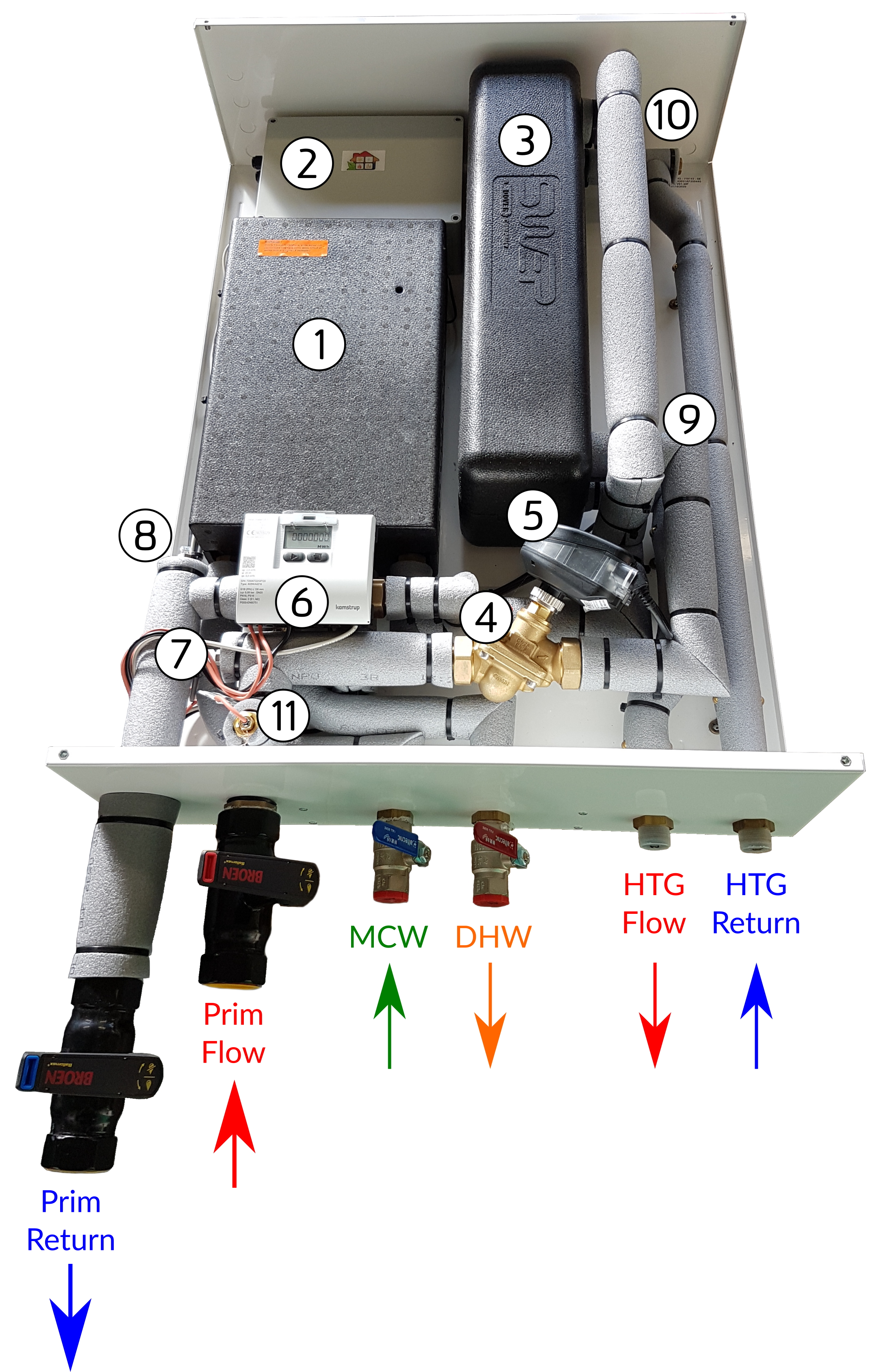

| Item No. | Description | Pt. No. |
|---|---|---|
| 1 | SLIM HIU | 70TILSLIM |
| 2 | Node-iHIU Control | 70DATA-Extra-Control |
| 3 | CH Plate Heat Exchanger | 7028768 |
| 4 | CH Control Valve | 70610 |
| 5 | CH Control Valve Actuator | 70NOVO003Z8500 |
| 6 | Heat Meter | 70HM403-2.5-G1B-130 |
| 7 | Primary Flow Temperature Sensor | 70HSF51862 |
| 8 | Primary Return Temperature Sensor | 70HSF51862 |
| 9 | CH Flow Temperature Sensor | 70HSF51862 |
| 10 | Manual Air Vent | N/A |
| 11 | Heat Meter Flow Temperature Sensor | N/A |
| 12 | DHW Plate Heat Exchanger | 7066561 |
| 13 | DHW Stepper Control Valve | 70HSF51495 |
| 14 | Universal HIU Controller | 70HSFCONTROL |
| 15 | DHW Flow Sensor | 70HSF50274 |
| 16 | DHW Temperature Sensor | 70HSF52727 |
| 17 | Primary Return Temperature Sensor | 70HSF52726 |
| 18 | Primary Flow Temperature Sensor | 70HSF52727 |
| Not Shown | Optional Differential Pressure Sensor | 70200216-2 |
Datasheet
 | DATA Extra Spec. Sheet |
Schematic diagram
HIU

Installation

Download
 | DATA Extra Install Schematic |
Wiring diagrams
Wiring Schematic

Download
 | DATA Extra Wiring Diagram Download a copy of the DATA Extra Wiring diagram here |
Technical Data
| Primary | |
|---|---|
| Nominal primary supply temperature | 85°C |
| Maximum primary supply temperature | 90°C * |
| Minimum primary supply temperature | 55°C ** |
| Maximum primary differential pressure | 250kPa |
| Minimum primary differential pressure | 50kPa *** |
| Pressure class DH circuit | PN16 |
| Domestic Hot Water | |
| Nominal DHW supply temperature | 55°C |
| DHW Set Range | 45°C to 60°C |
| Domestic Hot water heat exchanger (DHW) | E8LAS‐40 |
| Keep Warm Modes | Economy / Comfort |
| Keep Warm Temperature | 25°C to 60°C |
| Keep Warm Duration | 0 to 120 mins or Always On |
| Max Return Temperature during Keep Warm Mode | DHW Setpoint -2°C |
| DHW Max pressure | 6 Bar |
| Pressure class DHW circuit | PN10 |
| DWH Priority | Multi-Stage **** |
| Central Heating | |
| Maximum flow temperature | Primary T -5°C |
| Return Temp Limit Range | 35°C to 55°C |
| CH Limit Range | 30°C to 80°C |
| Central heating heat exchanger (CH) | B25TH‐30 |
| Pressure class CH circuit (3 bar safety valve) | PN16 |
| CH working pressure | N/A (By Installer) |
| Nominal pump pressure | 20 kPa (Adj. 0-70) |
| Maximum recommend flow rate | 750 l/hr |
| General | |
| Primary connections | DN32 Female |
| Mains & DHW connections | ¾” Female |
| Central heating connections | ¾” Female |
| Casing width | 653mm |
| Casing height | 900mm |
| Casing depth | 225mm |
| Casing Material | Steel |
| HIU Insulation Material | EPP Expanded Polypropylene |
| Pipework Insulation Material | Grey Polyethylene Foam |
| Maximum Heat Losses | <50W (1.2 kWh/day) |
| Weight (basic version) | 35kg Approx |
| Electrical supply info | 230V 50Hz - 0.64A |
| Power consumption per year | circa 45kWh |
| Fuse ratings | 3 Amp |
| Sensors | NTC 10kohm @ 25°C |
.* Maximum primary supply temperature 100°C for momentary spikes.
.** Minimum required DH supply temperature is DHW setpoint + 5°C with a minimum of 55°C.
.*** Depends on requested DHW output and available DH supply temperature.
.**** See Multi-Stage DHW Priority example below.
DHW Performance
DHW Performance Table

DHW Power Chart for 10-55°C

Primary Return Temperatures for 10-55°C

Primary Flow Rates for 10-55°C

Primary Pressure Drop for 10-55°C

Domestic Hot Water Pressure Drop for 10-55°C

Central Heating Temperature Curves
Central Heating Temperature Curves for 70-35°C
Primary Return Temperature

Primary Flow Rate - CH

Secondary Flow Rate - CH

Pressure Drops

General Plumbing Requirements
NEW COMPLETE SYSTEM INSTALLATIONS: When carrying out a completely new heating system installation in a new build property or a first time installation in an existing property, then the heating system must conform to current building regulations Part L1a. All new domestic heating systems must have a minimum of two heating zones. Each of these zones should be controlled by a thermostat and zone valve. Alternatively individual electronically controlled Thermostatic Radiator Valves may be fitted. If domestic hot water is provided by a storage system then the storage system or cylinder will require separate time and temperature control.
All radiators must have TRV's fitted in all rooms except bathrooms and any rooms where a thermostat is located. The exception to this are single storey, open plan dwellings where the living area is more than 70% of the total usable floor area. Then this type of dwelling can be controlled as one zone.
EXISTING INSTALLATIONS: When carrying out boiler replacements on an existing system, the regulations do not require separate zoning of the upstairs and downstairs and compliance with the regulations can be achieved by a single room thermostat or programmable room thermostat. It is however recommended that TRV's are fitted to all rooms except the bathrooms and the room where a thermostat is located.
The appliance must be installed in accordance with, and comply to, the current: IEE Regulations, Building Regulations, Building Standards (Scotland) (Consolidation), Building Regulations (Northern Ireland), local water by-laws, Health & Safety Document 635 (The Electricity at Work Regulations 1989) and any other local requirements.
BRITISH & IRISH STANDARDS Where no specific instruction is given, reference should be made to the relevant British and/or Irish Standard codes of Practice.
- BS7074:1 Code of practice for domestic and hot water supply
- EN12828 Central heating for domestic premises
- BS7593 Treatment of water in domestic hot water central heating systems
- ECTI National rules for electrical installations
POTABLE WATER: All seals, joints and compounds (including flux and solder) and components used as part of the secondary domestic water system must be approved by WRAS.
FITTING AND MODIFICATIONS: Fitting the appliance and any controls to the appliance may only be carried out by a competent engineer. Any misuse or unauthorised modifications to the appliance or associated components and systems could invalidate the guarantee and may lead to serious injury or even death. The manufacturer accepts no liability arising from any such actions, excluding statutory rights.
SERVICING: The end user should be advised to have the system serviced annually by a competent engineer. Contact Thermal Integration Ltd for a list of approved engineers. Approved spares must be used to help maintain the economy, safety and reliability of the appliance. The service engineer must complete the Service Record after each service.
General Wiring Requirements
These instructions apply in the UK and Ireland only and must be followed except for any statutory obligations. Component specific electrical information may also be supplied in support of these instructions, however if there is any doubt please contact Thermal Integration Ltd. (Tel: 0345 2411441)
FAILURE TO INSTALL APPLIANCES CORRECTLY COULD LEAD TO PROSECUTION.
The appliance must be installed in accordance with, and comply to, the current: IEE Regulations, Building Regulations, Building Standards (Scotland) (Consolidation), Building Regulations (Northern Ireland), local water by-laws, Health & Safety Document 635 (The Electricity at Work Regulations 1989) and any other local requirements.
BRITISH & IRISH STANDARDS: Where no specific instruction is given, reference should be made to the relevant British and/or Irish Standard codes of Practice.
- BS7074:1 Code of practice for domestic and hot water supply
- EN12828 Central heating for domestic premises
- BS7593 Treatment of water in domestic hot water central heating systems
- ECTI National rules for electrical installations
CAUTION: ISOLATE THE MAINS SUPPLIES BEFORE STARTING ANY WORK AND OBSERVE ALL RELEVANT SAFETY PRECAUTIONS.
Danger of short circuit: When connecting the cables ensure that no cable pieces fall inside the control panel.
The Mains supply to the appliance must be through a fused double pole isolator situated next to the appliance. The isolator must have a contact separation of 3mm minimum in all poles and should isolate the appliance and all associated controls.
Unless otherwise stated, all Heat Interface Units should be connected to a mains 230V 50Hz Supply fused at 3 Amps.
All electrical connections with the Heat Interface Unit control panel are clearly marked as follows:
- L = Live 230V
- N = Neutral
- E = Earth


Any additional mains cable should comply fully with the current I.E.E. wiring regulations. It must have a minimum section of 0.75mm2 and be capable of withstanding a minimum of 85°C.
Factory Settings
DHW Settings
The DHW settings are factory set, and these can only be changed by connecting a laptop directly to the SLIM HIU communication cable and using the HIU Monitor Application Software available from Thermal Integration. If the DATA Extra HIU is connected to a BMS, it is possible to alter the settings through the BMS ModBus interface.
The factory settings are as follows:-
| Setting | Limits | Set Value |
|---|---|---|
| Temperature - DHW | 45 - 60°C | 55°C |
| Pressure | Manual / Auto | Auto |
| Ecoheat Time (keep warm) | Off,15, 30, 60, 120, Always | Off |
| Ecoheat Temperature | 25 - 60°C | N/A |
| Legionella Prevention Cycle | On / Off | Off |
| District Heating Warmup Boost | 8 - 20 l/min | 20 l/min |
Central Heating Settings
| Setting | Limits | Set Value |
|---|---|---|
| Temperature - CH | 20 - 80°C | 60°C |
| Pump Over-run | any | 60 secs |
| Return Temperature Monitoring | On / Off | Off |
| Return Temperature Limit | 30 - 55°C | 55°C* |
| CH Control Valve Pre-set | 10 - 100% | 100% |
- If the Return Temperature Monitoring function is set to 'Off' the Return Temperature Limit is irrelevant.
Multi-Stage DHW Priority
If DHW priority is not suitable for the installation location (for instance in a restaurant or hair dressers, where hot water draw-offs may be frequent and therefore hold off the heating output), the primary flow rate available for the HIU to operate simultaneously in both DHW and CH modes, does not need to be the sum of the two circuits. This is due to the Multi-Stage DHW Priority feature built into the HIU software.
This feature allows peek or multi-staged flow limits to be set, which enables the DHW priority to be off-set against a proportion of the heating flow. Although it is possible to set specific flow rates and reductions, An example of the basic principle is explained below:-
DHW primary flow rate =
0 to 25%, no effect on the heating output
25 to 50%, heating output reduced by 25%
50 to 75%, heating output reduced by 50%
75 – 100%, heating off completely.
Adjusting Temperatures and Settings
Domestic Hot Water
Instead of working in isolation, the SLIM HIU which provides the domestic hot water function of the DATA Extra HIU, is connected to the Node-iHIU controller and can be accessed through the BMS. It is possible to adjust the hot water temperature, select the keep warm function, view performance graphs and access HIU alarms.
We have a separate Wiki page for the SLIM HIU here. This includes a User and Installation Manual, which gives information specifically relating to the SLIM HIU.
Central Heating

The Danfoss AB-QM Pressure Independent Control Valve has been used by Thermal Integration for many years now as a reliable means to control flow rates.
Depending on the design flow rate of the central heating circuit, the AB-QM control valve can be adjusted to limit the flow rate into the primary side of the plate heat exchanger. Adjustments can be carried out while the system is in use, and without the need for any tools. Reducing the Primary flow rate will reduce the temperature of the water flowing into the central heating circuit.
The DATA Extra HIU is fitted with the DN25 valve and details on its adjustment are shown on page 2 of the Installation Guide below, with related flow rates shown on page 4.
 | Danfoss AB-QM Datasheet |
|
| Danfoss AB-QM Installation Guide |

The actuator used in the DATA Extra HIU is the Danfoss NovoCon and it is connected to the NODE-iHIU Controller via a digital cable. The actuator is set-up in our factory using the Danfoss NovoCon Configuration tool to work with the DN25 AB-QM Valve and with a 6 sec/mm Actuator speed, specifically for heating systems. The dip switches are set as per the photograph below and they must NOT be changed.

The NODE-iHIU controller accurately positions the NovoCon actuator to control the flow into the plate heat exchanger, and by doing so, it is able to accurately control the central heating output temperature and limit the Primary return temperature, if the central heating system is unbalanced.
The Primary return temperature function is disabled by default, however when enabled, the default limit is set to 55°C. It is possible to alter this temperature by accessing the HIU via a ModBus connection.
|
| Novocon Datasheet |
|
| Novocon Installation Guide |
Status indicator LED's

SLIM HIU - DHW Status
The SLIM HIU Status LED is visible through a small hole in the case of the unit, and has 5 possible modes as follows:-
- Green blinking (slow): Standby condition
- Blue blinking: Domestic Hot Water Mode / Tap draw-off
- Red blinking: Error
- White continuous: Service mode (installer only)
- No LED: HIU is switched off
Danfoss NovoCon - CH Status
The NovoCon Actuator has a series of 5 LED's on the side of the body, and various combinations show the position / status of the actuator. Common combinations are shown below, refer to page 4 of the NovoCon Datasheet for an explanation of all other combinations.


Heat Meters
Below are links to various heat meter models supplied by Thermal Integration, however other heat meter models maybe available.
Heat Meter Mounting
The Heat Meter body is positioned in the Primary Return pipe of the HIU, with a temperature sensor connected into rear of the body and a second temperature sensor mounted into the Primary Flow pipe. Although it is possible to fit various models of Heat meter into the HIU, it is important that the heat meter is designed for mounting in the return pipe, has 3/4" connections spaced at 130mm and a nominal flow rate of 2.5m3/hr.
The Heat Meter display can be left mounted on the body, or it can be mounted external to the HIU casing. Slide the heat meter display up to remove it from the body, and route the cables through the cable entry slot at the bottom left of the casing. Screw the heat meter mounting bracket (supplied with the HIU) to the wall, and slide the display down on to it. Finally clip the cables neatly to avoid snagging.
It is NOT possible to increase or reduce the length of the heat meter cables or sensors. Therefore the heat meter display will need to be mounted close to the HIU.
