Installation Instructions for the Data HIU
Explanation of symbols and abbreviations
Symbols

Abbreviations

Introduction

|
1 Primary circuit strainer (Pt. 70HSF51890) 2 Back casing (Pt. 70HSF51990) 3 Primary flow temperature sensor (Pt. 70HSF52727) 4 Heat meter sensor pocket 5 Automatic air vent (CH) (Pt. 70HSF51878) 6 Electronics 230 V (Pt. 70HSF53051) 7 Electronics 24 V (Pt. 70HSF53051) 8 Heat exchanger (CH) (Pt. 70HSF52806) 9 DHW Temperature sensor (Pt. 70HSF52727) 10 Heat exchanger (DHW) (Pt. 70HSF52806) 11 CH pump (Pt. 70HSF53063) 12 DHW control valve (Pt. 70HSF51495) |
13 DHW primary return temperature sensor (Pt. 70HSF53052) 14 CH strainer (Pt. 70HSF51890) 15 Filling point 16 Flow sensor (Pt. 70HSF50274) 17 Pressure/temperature gauge (Pt. 70HSF51840) 18 Temperature/pressure sensor CH supply (Pt. 70HSF53056) 19 Pressure relief valve (3 Bar) (Pt. 70HSF53055) 20 CH primary return temperature sensor (Pt. 70HSF53052) 21 Heat meter spool piece 22 Central heating control valve (Pt. No. 70HSF51495) 23 Expansion vessel (Pt. No. 70HSF53057) 24 Expansion vessel bleed valve |
Available Options
The unit has several options available depending on requirements. The basic unit can be equipped with any combination of the following:
- Option A1: Spool piece, used when neither option A2 or A3 are required.
- Option A2: Landlord security valve, allows the landlord to remotely isolate the unit from the district heating network if required.
- Option A3: Differential pressure control valve, to balance differential pressures between the primary flow and return. Only required where the differential pressure exceeds 250kPa. (Max 450kPa)
- Option B: Water hammer arrester, reduces water hammer within the DHW circuit.
- Option C: DHW recirculation unit, to provide constant circulation of DHW throughout the property in order to allow quicker response times at the tap where extended pipe runs are unavoidable. Note: The unit must be set to 'Comfort' Mode by the installer, when this option is fitted.
- Option D: Decorative casing, attractive white painted steel casing.
- Option E1: Standard Output Domestic Hot Water, up to 65kW (at 10-60°C)
- Option E2: Plus output Domestic Hot Water, up to 80kW (at 10-60°C)
- Option F: Flushing Bypass for connecting to the primary flow and return pipework (External to the unit)

Dimensions

Technical Data
| DESCRIPTION | DATA |
|---|---|
| Nominal primary supply temperature | 80°C |
| Maximum primary supply temperature | 85°C |
| Minimum primary supply temperature | 55°C * |
| Nominal DHW supply temperature | 55°C |
| DHW Set Range | 45°C to 60°C |
| Return Temp Limit Range | 35°C to 65°C |
| CH Limit Range | 30°C to 80°C |
| Primary connections | ¾” Female / 18mm |
| Mains & DHW connections | ¾” Female / 18mm |
| Central heating connections | ¾” Female / 18mm |
| Pressure relief | 15mm |
| Domestic Hot water heat exchanger (DHW) | E8LAS‐40 |
| Central heating heat exchanger (CH) | E8LAS‐40 |
| Maximal primary differential pressure (without dP regulator) | 250kPa |
| Maximal primary differential pressure (with dP regulator) | 450kPa |
| Minimal primary differential pressure | 50kPa ** |
| Pressure class DH circuit | PN16 |
| Pressure class CH circuit (3 bar safety valve) | PN10 |
| Pressure class DHW circuit | PN10 |
| CH Maximum working pressure | 2.5 Bar |
| Casing width | 490mm |
| Casing height | 640mm |
| Casing depth | 275mm |
| Casing Material | EPP Expanded Polypropylene |
| Maximum Heat Losses | 50W (1.2 kWh/day) |
| Typical Heat Losses (DHW Only, Keep Warm) | 25W |
| Weight (basic version) | 24kg *** |
| Electrical supply info | 230V 50Hz |
| Fuse ratings | 3 Amp |
| Sensor DHW | NTC 10kohm @ 25°C |
| Keep Warm Modes | Economy / Comfort |
| Max Return Temperature during Keep Warm Mode | DHW Setpoint - 2°C |
.* Minimum required DH supply temperature is DHW setpoint + 5°C with a minimum of 55°C.
.** Depends on requested DHW output and available DH supply temperature.
.*** Unit weight may vary depending on the optional components built into the unit
Application
The Data twin plate HIU is used to provide hot water and central heating in properties connected to a district heating system using a centralised boiler. Please keep the following conditions in mind during installation:
- The unit must be installed in a frost free area.
- The unit must not be exposed to direct sunlight.
- Ambient temperature should be between +5°C and +40°C.
- Humidity should be between 10% and 85%.
- The unit must be connected to a fused double pole isolator.
- The unit uses 230 VAC. Use caution when handling. Contact may lead to shock, burns or electrocution.
- Temperatures of components in the unit and connected to the unit can reach high temperatures. Contact may lead to burns.
Status indicator LED

- Green blinking (slow): Normal condition
- Green blinking (fast): Heating demand
- Blue blinking: Domestic Hot Water Mode / Tap draw-off
- Red blinking: Error
- White continuous: Service mode (installer only)
- No LED: HIU is switched off
Operation
Central Heating
The heat exchanger physically separates the district heating network and the central heating circuit. The application minimises the risk of contamination of district heating water as well as the risk and consequences of leakage in the central heating system.

Components, pipes and radiators in, and connected to the unit may be hot. The DATA heat interface unit is designed for use with centralised heating systems up to 85°C. The pipes and components in the unit and the pipes and radiators in the central heating installation can reach temperatures of 80°C and contact may lead to burns.
Domestic Hot Water
The unit is equipped with single walled plate heat exchangers. The front heat exchanger transfers the heat from the district heating system to the DHW. The electronics within the unit, together with domestic hot water control valve, temperature sensors and flow sensor, regulate the temperature of the hot water to it's set point (As Standard 55°C).
Each HIU has two domestic hot water keep hot modes, Eco or Comfort mode. These can only be selected during commissioning or by a trained engineer.
The default setting is Eco mode, and this can be specified to run for 0 minutes (which turns the feature off all together), 15, 30, 60 or 120 minutes after the last hot water draw off. In Eco mode the heat exchanger is kept to a specified temperature (between 25 and 60 Deg C) for the selected period of time and after this period of inactivity has elapsed the stepper motor closes completely and the temperature in the domestic hot water circuit is allowed to drop through natural dissipation to minimize energy consumption. If a hot water draw off is made any time throughout the Eco mode function the unit will deliver hot water as usual and the Eco mode function will begin counting down for the selected time once again. In Comfort mode the heat exchanger is continuously supplied with a trickle of primary water for quicker hot water delivery, however energy consumption will be slightly higher than if the unit was set in Eco mode.
To prevent legionella from growing the heat exchanger is heated to 57°C for at least 30 minutes every 24 hours. (it is not possible to specify the time at which this occurs)
The hot water temperature is regulated to approximately 55°C. If there is a power outage during DHW draw off, units not fitted with a landlord security valve will stop regulating the hot water temperature. This may lead to a hot water temperature that is higher or lower than 55°C. Hot water can cause burns.
Priority Switching
The unit is fitted with domestic hot water priority switching. When hot water is drawn off, the central heating control valve will close, diverting all primary flow to heat the domestic hot water circuit. Primary flow to the central heating is cut off during hot water delivery. Primary flow to the central heating is resumed after the hot water draw off has finished.
General Plumbing Requirements
NEW COMPLETE SYSTEM INSTALLATIONS: When carrying out a completely new heating system installation in a new build property or a first time installation in an existing property, then the heating system must conform to current building regulations Part L1a. All new domestic heating systems must have a minimum of two heating zones. Each of these zones should be controlled by a thermostat and zone valve. Alternatively individual electronically controlled Thermostatic Radiator Valves may be fitted. If domestic hot water is provided by a storage system then the storage system or cylinder will require separate time and temperature control.
All radiators must have TRV's fitted in all rooms except bathrooms and any rooms where a thermostat is located. The exception to this are single storey, open plan dwellings where the living area is more than 70% of the total usable floor area. Then this type of dwelling can be controlled as one zone.
EXISTING INSTALLATIONS: When carrying out boiler replacements on an existing system, the regulations do not require separate zoning of the upstairs and downstairs and compliance with the regulations can be achieved by a single room thermostat or programmable room thermostat. It is however recommended that TRV's are fitted to all rooms except the bathrooms and the room where a thermostat is located.
The appliance must be installed in accordance with, and comply to, the current: IEE Regulations, Building Regulations, Building Standards (Scotland) (Consolidation), Building Regulations (Northern Ireland), local water by-laws, Health & Safety Document 635 (The Electricity at Work Regulations 1989) and any other local requirements.
BRITISH & IRISH STANDARDS Where no specific instruction is given, reference should be made to the relevant British and/or Irish Standard codes of Practice.
- BS7074:1 Code of practice for domestic and hot water supply
- EN12828 Central heating for domestic premises
- BS7593 Treatment of water in domestic hot water central heating systems
- ECTI National rules for electrical installations
POTABLE WATER: All seals, joints and compounds (including flux and solder) and components used as part of the secondary domestic water system must be approved by WRAS.
FITTING AND MODIFICATIONS: Fitting the appliance and any controls to the appliance may only be carried out by a competent engineer. Any misuse or unauthorised modifications to the appliance or associated components and systems could invalidate the guarantee and may lead to serious injury or even death. The manufacturer accepts no liability arising from any such actions, excluding statutory rights.
SERVICING: The end user should be advised to have the system serviced annually by a competent engineer. Contact Thermal Integration Ltd for a list of approved engineers. Approved spares must be used to help maintain the economy, safety and reliability of the appliance. The service engineer must complete the Service Record after each service.
General Wiring Requirements
These instructions apply in the UK and Ireland only and must be followed except for any statutory obligations. Component specific electrical information may also be supplied in support of these instructions, however if there is any doubt please contact Thermal Integration Ltd. (Tel: 0345 2411441)
FAILURE TO INSTALL APPLIANCES CORRECTLY COULD LEAD TO PROSECUTION.
The appliance must be installed in accordance with, and comply to, the current: IEE Regulations, Building Regulations, Building Standards (Scotland) (Consolidation), Building Regulations (Northern Ireland), local water by-laws, Health & Safety Document 635 (The Electricity at Work Regulations 1989) and any other local requirements.
BRITISH & IRISH STANDARDS: Where no specific instruction is given, reference should be made to the relevant British and/or Irish Standard codes of Practice.
- BS7074:1 Code of practice for domestic and hot water supply
- EN12828 Central heating for domestic premises
- BS7593 Treatment of water in domestic hot water central heating systems
- ECTI National rules for electrical installations
CAUTION: ISOLATE THE MAINS SUPPLIES BEFORE STARTING ANY WORK AND OBSERVE ALL RELEVANT SAFETY PRECAUTIONS.
Danger of short circuit: When connecting the cables ensure that no cable pieces fall inside the control panel.
The Mains supply to the appliance must be through a fused double pole isolator situated next to the appliance. The isolator must have a contact separation of 3mm minimum in all poles and should isolate the appliance and all associated controls.
Unless otherwise stated, all Heat Interface Units should be connected to a mains 230V 50Hz Supply fused at 3 Amps.
All electrical connections with the Heat Interface Unit control panel are clearly marked as follows:
- L = Live 230V
- N = Neutral
- E = Earth


Any additional mains cable should comply fully with the current I.E.E. wiring regulations. It must have a minimum section of 0.75mm2 and be capable of withstanding a minimum of 85°C.
Schematic

Wiring Diagrams
Power Supply
The heat interface unit is equipped with a wiring centre that converts the 230 VAC power supply to 24 VDC and powers the CH pump and optional DHW pump. It also houses the main fuse for the unit.

Room thermostat
The unit can be equipped with a on/off thermostat that has potential free contacts or a Honeywell round on/off (T87G2014) thermostat with power stealing technology.
Full Wiring Diagram with Ethernet Billing

Installation Requirements
Components, pipes and radiators in, and connected to the unit may be hot. The DATA heat interface unit is designed for use with centralised heating systems up to 85°C. The pipes and components in the unit and the pipes and radiators in the central heating installation can reach temperatures of 80°C and contact may lead to burns.
To ensure the life expectancy of the unit, the system must meet certain requirements. Keep following conditions in mind during installation:
- Maximum pressure supplied by the district heating network is 10 bar.
- Maximum differential pressure supplied by the district heating network is 250 kPa. (450 kPa when differential pressure valve is fitted)
- Maximum supplied temperature by the distict heating network is 90°C.
- Minimal supply temperature is setpoint DHW + 5°C.
Central heating
Before the unit is commissioned, the central heating circuit must be fitted with an automatic bypass valve to maintain a minimal flow rate and regulate pressure across the system. The valve must be installed between the central heating supply and return, noting the direction of flow.

ABV = Automatic Bypass Valve
NOTE For optimal energy efficiency and comfort, it is of the utmost importance to hydraulically balance the CH system correctly. For the same purpose it is advisable to design the CH system in such a way that the CH return temperatures are as low as possible.
* Artificially softened water must not be used to fill the central heating system
DHW Recirculation Unit
The DHW recirculation unit is an available option within the unit. The circulation system connected to the unit must not contain any closable valves. Applying valves to the system can cause the pump to overheat due to insufficient flow.

Keep following condition in mind during installation:
- Maximum pressure supplied by the domestic water circuit is 10 bar.
- All seals, joints and compounds (including flux and solder) and components used as part of the secondary domestic water system must be WRAS approved.
Installation Setup
Parts Supplied and Required for Installation

Connections

Stage 1 - Pre-Fix Bracket Positioning
The following dimensions are for the extended pre-fix kit. If a flushing by-pass is to be fitted, please refer to the relevant page.
- Mark out the wall with the fixing points using the dimensions shown below.
- Drill holes using a suitable drill bit to suit wall plugs provided in accessory pack.
- Using a level, fit first fix brackets to wall.
- Continue with external pipework as required. With isolating valves closed the systems can be filled for testing.

Mounting to a plywood wall: Minimal plywood thickness must be 18 mm. Make sure that the back wall is at least 50 mm wider than the unit to ensure a proper support. Make sure the drill markings are aligned and leveled. Drill holes of Ø4 mm on the marked locations 40 mm deep. 4 holes are drilled for the fix rail unit and another 4 for the unit. Mount the fix rail firmly to the wall using the enclosed screws.
Mounting to a concrete wall: Make sure the wall is robust and of good quality. Avoid hollow walls and make sure that the screws are not placed in the flushings of a brick wall. Drill holes of Ø10 mm on the marked locations 60 mm deep. 4 holes are drilled for the fix rail unit and another 4 for the unit. Mount the fix rail firmly to the wall using the enclosed screws and plugs.
Stage 2 - HIU Preparation
- Remove casing carefully. If the unit is supplied with a security bracket, this will first need to be removed.
- Remove bag of accessories.
- Remove protective caps from connections

Stage 3a - Fixing HIU

- Please use the enclosed screws and plugs to mount the unit.
- The fixing must be able to withstand at least the unit weight. Please allow for a minimum of 30Kg.
- There are 4 lower connections if the Domestic Hot Water recirculation unit is not fitted.
- Place washers into lower union connections.
- Lift the HIU into position and with unit slightly tilted forwards, position onto lower first fix bracket, making sure washers remain in place.
- Tighten connections.
Stage 3b - Pipework connections

Stage 4 - Fitting a Heat Meter
Units are typically supplied with heat meters factory fitted as per requirements, however a heat meter can be fitted by following these steps.
1. Remove Spool Piece

2. Install Heat Meter

Stage 5 - Filling the Heating System
The method of filling the CH system must comply with the current water supply (water fittings) regulations and use approved equipment. For GB Please refer to Guidance G24.2 and recommendation R24.2 of the water regulations guide. For IE Please refer to the current edition of I.S. 813 "Domestic Gas Installations".
A WRAS approved filling loop should be used for connecting the mains water supply to the CH system so that the system can be filled on installation or whenever water pressure has been removed for system modifications, etc. An approved double check valve must be permanently fitted to the mains water circuit to provide backflow prevention and the temporary filling hose must be removed and connections capped after use.
Failure to isolate and disconnect the temporary filling hose after use, may result in the central heating system being over-pressurised and could cause damage to central heating components.
The nominal operating pressure of the central heating system should be between 1 and 2 Bar.

Stage 6 - Bleeding the Unit
To ensure the unit functions properly, it must be bled first. This can be done from two places within the unit. The system must also be bled at the radiators.
- Disconnect the power to the unit
- Bleed the unit at the points shown below and the bleeding points connected to the radiators.
- Start at the lowest bleeding point and work upwards ending at the highest point in the property.
- Bleed the system until all air is expelled.
- Option for quick filling CH system (only at position 2): For quick filling of the CH system, turn the red cap of the automatic air vent counterclockwise. Set the red cap in the original position after filling.

Stage 7 - Programmer and Room Thermostat Connection
The unit can (optionally) be connected to a programmer / room thermostat, to control central heating timing and / or temperature.

Connecting the programmer / room thermostat:
- Locate the brown and white twin cable (600mm Long) at the back of the HIU electronic controller, remove and discard the temporary coupler plug.
- Connect a VOLT FREE programmer / room thermostat (sold separately) across the brown and white cables.

Stage 8 - Connect Power
1. Close all isolation valves in the property.
2. Check all coupling nuts for leakage. (nuts may become loose during transport)
3. Make sure the electronics are securely mounted to the frame and avoid cables and pulse pipes from fouling the casing.
4. Connect the units power cables (A) to the power outlet.
- Blue cable: N (Neutral)
- Brown cable: L (Live)
- Green/yellow cable: E (Earth)
5. Slowly open the filling loop valves to pressurize the unit and check for leakage.
6. Switch on the power supply to the unit. The LED should show a green blinking light (B).
7. Slowly open the district heating flow valve (C) and check for leakage.
8. Slowly open the district heating return valve (D) and check for leakage.
9. Slowly open the central heating flow valve (E).
10. Bleed the system. Start at the lowest point and work your way to the highest bleed point. Please refer to the chapter Bleeding the system.
11. Slowly open the central heating return valve (F).
12. Check that the central heating controls are calling for heat and the system begins to warm.
13. Slowly open a hot tap in the property. Check to see if the units LED shows a blue blinking light (B). Open the hot tap completely when the system is fully bled and leave it running for approximately 5 minutes. After 3 to 5 minutes check the water temperature at the tap is between 45°C and 60°C (Depending on the setpoint).
14. Bleed the unit (G)Please refer to the chapter Bleeding the unit.
15. Close the hot tap in the property. The LED will now show a green blinking light (B)

Adjusting Settings
The Data requires connection to either a PC running the commissioning software, or by the use of an iHIU Controller, in order to adjust settings.
End users cannot adjust settings, unless an iHIU Controller is used.
PC Software
The software is made freely available, along with training, to registered commissioning engineers. Please contact Thermal Integration for further information.
The software allows one to adjust the following settings:
| Setting | Options | Default |
|---|---|---|
| Domestic Hot Water Temperature | 45°C to 60°C | 60°C |
| Primary Differential Pressure | Auto or Manual from 0.3 to 2.0 bar | Auto |
| Warmup Boost Flow Rate | 8 to 20 l/min | 12 l/min |
| Return Temperature Limit | Disabled or Enabled from 35°C to 65°C | Disabled |
| Maximum Central Heating Temperature | 30°C to 80°C | 80°C |
| Central Heating Pump Timeout | 0 to 30 minutes | 15 minutes |
iHIU Controller
The iHIU Controller is a miniature Linux web server that can be supplied separately to provide more advanced control and monitoring of the Data HIU. The controller is typically mounted within the casing of the HIU, with an option for a display on the front of the HIU.
The controller provides a WiFi zone, and can log onto existing networks through either WiFi or Ethernet to gain access to the internet. The HIU can then be controlled directly from other devices on the local network, such as smartphones. Once connected to the internet the system can provide remote control and monitoring services, as well as many other features, some of which are listed below:
- Browser based cross platform interface that adjusts to screen size
- Allows setting of all the parameters available to the PC software, except via a browser
- Control over central heating as well as other settings via Google Calendar
- Remote commissioning
- Remote fault alarms and message forwarding vi email or SMS
- Voice control over services via Android app
- Connection to Energy Saving Trust's Embed Database for free and secure online storage of all system data
Securing the casing
To secure the unit, a metal security casing is fitted. The casing will obstruct from removing the EPP casing without damaging the seal. It also functions as a mount for the display of the heat meter.
- Mount the display of the heat meter onto the metal security casing.
- Move the metal security casing into position (1) and guide the heat meter cables through the casing. Make sure the cables are not obstructed or tangled.
- Check to see if the metal security casing is aligned with the EPP casing (2).
- Fix the metal security casing with the enclosed screw and seal. Make sure the order of assembly is as shown (3).

Service and Inspection
To ensure the unit functions properly, it is advised to periodically inspect the installation.
Maintenance and repairs should be carried out by recognised personnel only.
- Remove the power from the unit when performing maintenance and/or repairs.
- Connect the flow and return valve from the district heating network.
- Connect the flow and return valve on the unit.
- Check the unit for leaks.
- Check the primary and central heating strainer for debris and clean if necessary.
- Check valves for debris and clean if necessary.
- Check the unit operates satisfactorily in domestic hot water and central heating modes.
- The casing can be cleaned with a damp cloth. Do not use detergents of any kind.
CAUTION! The unit uses electrical components (230VAC and 24VDC). These components must stay dry at all times. Contact with these energized components can result in an electrical shock, burn, or electrocution.
Prolonged Absence
Do not switch off the unit during long absence or holiday. To prevent frost damage within the unit or the distribution network, the radiator and shutoff valves MUST remain open. Radiators can be switched to the frost protection position (slightly opened) and/or the room thermostat lowered to a MINIMUM of 10°C. It is recommended to flush all water tapping points and showers for at least 2 minutes after a long period of absence.
Draining the Unit
Should the unit need draining, please follow the below steps.
- Disconnect the power to the unit
- Open all radiator valves. When thermostatic valves are C fitted, switch them towards their maximum setting.
- Close the district heating flow and return valves (A)
- Remove the units front casing (B)
- Open the bleeding points in the unit (C). Please refer to the chapter Bleeding the unit.
- Connect a hose to the fill/drain valve (D)
- Drain the unit by opening the fill/drain valve (D). The bleeding points on the radiators must be open during this procedure.

Wilo Pump Settings

The heat interface unit is fitted with one of two central heating pumps. The pumps can be adjusted to fit the end users situation. By default, the pumps are placed in the maximum setting with a constant differential pressure.
Adjustments to the pump settings should be done by recognised personnel only. Please use caution when adjusting the unit. Parts can be hot or energized. Contact with these parts may lead to shock, burn or electrocution.
The Wilo pump is fitted with Red Knob technology. The knob opens the possibility to toggle between different settings:
- Constant differential pressure
- Proportional differential pressure
- Activating the pumps bleeding function
Bleeding

The pump will bleed itself at first startup. If the pump does not bleed itself, follow the steps below:
- Switch to bleeder mode
- Bleeder function will start after approximately 5 seconds and will take about 10 minutes to complete
- When bleeding is finished, switch the red knob back to the preferred setting
Setting up Pump Head
Pump settings are marked in metres pressure head, up to a maximum of 8m.
The differential pressure setting increases the head the pump generates as the flow accepted by the system increases. This setting can assist in reducing noise at low loads, as well as allow for long pipe runs where pressure losses become more significant at higher loads.
The constant pressure setting maintains a set head at all flow rates, modulating the pump up and down as load increases to maintain the same head.


The recommended setting is No. 2 (approximately 20 kPa) in constant pressure mode. 

Grundfos Pump Settings
|
The Grundfos pump has 3 control modes (proportional pressure, constant pressure and constant curve). Each control mode has 4 settings to choose from. The user interface has 1 push button, one red/green LED and 4 yellow LEDs.  |
|


Settings
When you switch on the pump, it runs with the factory pre-setting or the last setting. The display shows the current operation status.
- Press the button to switch to the setting view. The LEDs show the current setting for 2 seconds. (The default setting is curve 3)
- Release the button for more than 2 seconds. The user interface shows the current performance in "operation status".
- Press the button for more than 2 seconds and the pump switches to "setting selection". The LEDs flash and show the current setting mode. Please note that if the key lock is disabled, the pump will not switch to "setting selection". In this case, unlock the key lock by pressing the button for more 10 seconds.
- During a period of 10 seconds, press shortly on the button and the pump switches to the next setting.
- To select between the settings, instantly press the button until you find the setting you want. If you pass a setting, you need to continue until the setting appears again as it is not possible to go back in the settings menu.
- Release the button for more than 10 seconds and the user interface switches back to the performance view and the last setting is stored.
- Press the button and the display switches to the setting view and the LEDs show the current setting for 2 seconds.
- Release the button for more than 2 seconds and the user interface switches back to the performance view.
Performance View
While the pump is running, the first LED will show a green light. The following 4 LED’s will indicate the power consumption as shown in the table below.

DHW Recirculation Pump Option
|
The domestic hot water circulation pump is an available option within the unit. The pump is added to minimize delay in the delivery of domestic hot water at the draw off point in a closed DHW circulation circuit. It is generally used in systems where the domestic hot water needs to travel greater distances to its draw off point. Adjustments to the pump settings should be done by recognized personnel only. |
 |
Status indicator LED
| LED on (continuously): | Normal operation (pump is running) |
| LED blinking short, long: | Error due to low voltage |
| LED blinking short (4x), long: | Error due to pump speed feedback |
| LED blinking short (3x), long: | Error due to high temperature |
| LED blinking short (5x), long: | Pump rotor is blocked |
| LED On 200 msec., Off 200 msec., On 200 msec. | Air venting |
| LED On 50 msec., Off 50 msec., On 50 msec. | Stand-by |
Operation errors
| Problem | Cause | Solution |
|---|---|---|
| Pump not running | Not connected or connected correctly | Connect correctly |
| Pump too hot, dry operation or overheating protection active | Allow pump to cool down, pump restarts automatically | |
| Pump is blocked | Contact your supplier | |
| Pump is noisy | Not thoroughly air vented | Air vent the pump |
| Foreign objects in pump | Contact your supplier | |
| Worn bearing | Replace pump |
 |
Air venting the pump The pump has an air venting function that can be activated by turning the knob to position 7 for 5 seconds. Afterwards the desired position can be chosen. The procedure will take about 10 minutes. The procedure can be canceled by switching to position 3 and then back to position 7. Audible flow noises indicate that there is still air in the pump. Should this be the case the air venting procedure needs to be repeated. |
 |
Pump settings The circulation pump has 7 settings to choose from to accommodate different situations, position 1 being the lowest and 7 the highest setting. |
Differential Pressure Control Valve Option
The DATA, DIGI, SLIM and DATA SPLIT HIU's come as standard with a function to learn the differential pressure of the primary system during operation, adjusting its performance characteristics to suit. This self learning feature works by examining the effect of a valve movement compared to known characteristics, and hence determining what the differential pressure actually is. The self learning feature takes three seconds to perform, and is done every time a tap is opened and temperatures stabilise.
For DH systems with a differential pressure exceeding 250 kPa (with a maximum of 450 kPa), the option of a pre-mounted adjustable differential pressure control valve is available. The optionally fitted differential pressure control valve has a control range of 20 to 60 kPa and has DN20 bore. For optimal functioning of the HIU, the adjustable differential pressure control valve is set at its maximum of 60 kPa (default setting).
Adjustments to the differential pressure valve settings should be done by recognized personnel only.

The valve is easily set by means of a 4 mm hexagonal key. The maximum setting of 60 kPa is reached by turning the hexagonal key clockwise. The number of turns needed to adjust the valve to its maximum setting depends on what the current setting is. The maximum number of turn is 20, running from its minimum to maximum setting.
Troubleshooting for End users
What can you do?
Always take in account the safety of yourself and others when performing a troubleshoot.
| Leakage |
| 1. Close all valves on the plumbing bracket under the unit and the mains cold water feed. |
| 2. Contact your engineer. |
| Central Heating Circuit does not warm up |
| 1. Make sure the power cord is plugged in and turned on. If in doubt contact an electrician. |
| 2. Make sure the valves on the plumbing bracket are open (handle in vertical position). |
| 3. Check radiator valves are open and calling for heat. |
| 4. Check the programmer is set to ON, and calling for heat. |
| 5. Set the room thermostat higher. |
| 6. Problem solved? If not, contact your engineer. |
| No domestic hot water |
| 1. Check that the mains cold water valve is open. If not, open the main valve. |
| 2. Problem solved? If not, contact your engineer. |
| Tap water does not warm up |
| 1. Ensure that all valves on the plumbing bracket under the unit and the main valve are open. |
| 2. Make sure the power cord is plugged in and turned on. If in doubt contact an electrician. |
| 3. Problem solved? If not, contact your engineer. |
| Sound |
| NOTE: It is normal that the HIU makes noise when hot water or heating are active. Also, the electronic valves will make a light (buzzing) noise during movement. If the HIU starts to make any loud or disturbing noises, contact your installer. |
Troubleshooting (for Technicians)

Zenner Ultrasonic Heat and Cooling Meter
The Zenner Zelsius® C5 ultrasonic heat and refrigeration meter operates with an innovative ultrasonic technology, specially developed for domestic energy measurement. Thanks to a combination of modern measuring technology and a very compact design, this meter is perfectly suitable for recording all accounting data for measuring energy consumption in heating and/or refrigeration plants. The wear-free ultrasonic technology is impervious to debris, stable over the long term and is also reliable for very low volume flow rates.

Features
- Available as heat, cooling or combined heat/cooling meters
- Low design height
- Wired or wireless M-Bus (optional)
- 2 or 3 pulse inputs or outputs (optional)
- Any installation position (even overhead)
- Stores 24 months readings
- Powered entirely by the M-Bus network or M-Bus Master
- Up to 11-year battery backup, if disconnect from the M-Bus network
- Precise, long-term stable, wear-free
- Very wide dynamic range
- Conforms to MID, Class 2
Part Codes
ZE101C5 15MM C5 IUF Ultrasonic Heat/Cooling Meter. 0.6m3/h, 110mm body length
ZE102C5 15MM C5 IUF Ultrasonic Heat/Cooling Meter. 1.5m3/h, 110mm body length
ZE103C5 20MM C5 IUF Ultrasonic Heat/Cooling Meter. 2.5m3/h, 130mm body length
ZEC5MBO C5 M-Bus Output
ZEC5WMB C5 Wireless M-Bus Output
ZEC5PUO C5 Pulse/Radio Output
ZE200PO Pocket or Ball Valve 5.2mm, 50mm, 34.5mm
ZE015CO 15mm Couplings G3/4 R1/2 (pair)
ZE020CO 20mm Couplings G1B R3/4 (pair)
Further Documentation
- C5 IUF Conformity Cert MID
- C5 IUF Ultrasonic Heat Meter Data Sheet
- C5 Installation Guide
- LCD Manual
- C5 Wiring Guide
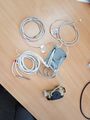
All Cables

Sensor Cables
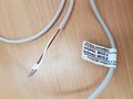
MBus Cables
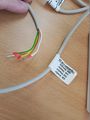
Pulse Cables


Flamcovent Clean Smart Dirt and Air Separator


Air bubbles and dirt particles are always present in the water of cooling and heating systems. The dirt can accumulate and cause blockages. The use of filters is not ideal because these do not trap smaller particles, silt up and then have to be regularly cleaned or replaced. Air and gases in a system are generally a consequence of activities performed, micro-leaks and of electrolysis and chemical processes in the water.Traditional de-aeration devices extract insufficient gases from the water, leaving microbubbles behind.
Air and dirt in a system cause problems such as unnecessary faults and extra wear or noise, but also lead to disruption of the system, lower heat transfer and reduced pump performance. The new Flamcovent Smart, Flamco Clean Smart and Flamcovent Clean Smart air and dirt separators are now offered as standard alongside all systems to provide reliable protection of the primary system.
- 60% better performance compared to conventional air and dirt separators.
- Suitable for temperatures of up to 120°C.
- Suitable for operating pressures of up to maximum 10 bar.
- Unique flow velocities, up to 3 m/s.
- Can be used with all kinds of pipework.
- Compact dimensions, light weight.
- Available in various sizes up to 2".
- Extremely low flow resistance and low loss of energy.
- Consistent performance throughout its service life.
{{#l:FlamcoventCleanSmart_ENG_DEF_2014.pdf}}
Guarantees and After Sales Backup for HIUs
Heat Interface Units (HIUs) carry the following guarantees as standard:
FACTORY WARRANTY
1. The warranty begins on the date of delivery. A dated delivery note will be issued to the customer and a copy will be stored by Heatweb Solutions.
2. 12 Months Parts and labour - Parts or labour proven to be defective will be replaced / repaired free of charge for a period of 12 months from date of delivery, provided the HIU is installed by a qualified engineer within 6 months of date of delivery.
- 24 Months Parts Only - Parts proven to be defective will be supplied free of charge (for fitting by others) for a period of 24 months from date of delivery.
3. Replacement of parts under warranty does not extend the duration of the warranty.
4. Any other costs are not covered by this warranty. All other damages of any nature whatsoever and howsoever arising, are expressly excluded from this guarantee.
5. The warranty conditions above only apply:
- a. In the UK only on items provided exclusively by Heatweb Solutions.
- b. If the product is installed by a Heatweb Solutions approved engineer in compliance with the installation instructions.
- c. The installer must complete the commissioning checklist in full at the time the HIU is installed. This checklist must be returned to Heatweb Solutions within 30 days of commissioning. Checklists are enclosed in the HIU installation instructions.
- d. If the installation complies with all current and relevant building regulations and codes of practice. (including the requirement to clean the primary and secondary heating systems and add corrosion inhibitor in line with BS7593:2006)
- e. If the product is used and maintained exclusively according to the manufacturer's instructions and proof of periodic inspection / maintenance by a Heatweb Solutions approved engineer is available.
- f. If the returned item is accompanied by a fully completed Heatweb Solutions Warranty Return Form.
6. Excluded are defects caused by:
- a. Failure to maintain in accordance with manufacturer’s instructions.
- b. Improper use.
- c. Any attempt at repairs / maintenance by un-qualified persons.
- d. where parts other than Heatweb Solutions Genuine Parts have been used in any service or repair.
- e. Lightning, fire or natural disasters.
- f. Deterioration and / or pollution from the district heating system or water network, either domestic hot water or heating side.
- g. PH values of the primary medium being less than 7.5 or greater than 9.0.
- h. Harmful additives to the heating water.
- i. Consumables as specified by us, including but not limited to: hoses, gaskets and batteries.
7. Report any faults to your installer, service engineer or Heatweb Solutions directly. Faulty parts must be accompanied by a fully completed Heatweb Solutions Warranty Return form, to be returned to Heatweb Solutions. Returned items remain the property of Heatweb Solutions Ltd.
The Heatweb Solutions Warranty Return Form can be requested by phone or email. Returns are not accepted unless expressly agreed in writing.
Transport risk of returned items lies with the sender. The shipping of replacement parts are the responsibility of the supplier.
8. If the HIU breaks down, we may ask you to pay us a deposit before we visit you to repair it. We will return the deposit in full if we find a fault that is covered by this warranty. We may keep the deposit if we cannot access your property at the time we had arranged with you to visit or we find other conditions of this warranty have not been met. A responsible adult must be at the property to give our engineer this access to the HIU.
9. COMMISSIONING
Heatweb Solutions offer commissioning services across the UK. The service includes:
- a. The fulfilment of the defined commissioning instructions.
- b. Completion and return of site wide commissioning paperwork.
- c. Rectification of any HIU problems.
- d. Confirmation of HIU performance to contract specifications.
- e. Engineer travel and subsistence.
Commissioning rates are charged on a whole day basis, and it is the responsibility of the client to ensure:
- a. Safe access to properties and HIUs
- b. Correct operation of central plant with delivery of heat to HIUs at specified temperatures, flow and pressures.
- c. All pipework has been correctly tested and flushed.
- d. Credit on billing system to enable security valve.
A minimum 2 weeks notice is required in writing to Heatweb Solutions before the requested commissioning date.
SERVICE
Technical assistance and engineer backup can be obtained by calling our offices:
- Commercial Sales and Operations: 0345 2411441 | @ enquiries@heatweb.com
- Training: 0345 2411441 | @ enquiries@heatweb.com
- Service: 0345 2411441 | @ service@heatweb.co.uk
FURTHER INFORMATION
The Heatweb Wiki website at www.heatweb.com/wiki contains information on all aspects of HIU design, function, and servicing, and is always the best place to visit for additional documentation or how to guides.
